I would like to summarize what I have learned about electronics per. autumn 2016. In addition, I will summarize and / or give a little more detail about the part of the electronics that I have built. The description is held up-to-date – also after 2016.
Command Station
The command station is the “control panel”. In the old analog days, there was a transformer with a button that could be rotated to determine how fast the train should run. In addition, there were some buttons for controlling turnouts, signals, etc. next to it:
 This and much more is now built into the command station:
 It is important to determine:
- If the command station should be able to work with a PC program to control the layout.
- If the command station is to be used without a PC.
- If the command station should be used with an additional throttle. See an example here.
- If the command station should be able to be used from an iPad and / or smartphone. If nothing else, you can use these devices to access JMRI, which again can control the command station – provided that the command station has some kind of PC interface.
- Which types of decoders should be used (DCC, M4/MFX, FX, Delta, Seletrix etc.)
- Which interface types should be supported, for example for feedback modules, extra throttles, other command stations, etc. It may, for example, be LocoNet, S88 (only feedback), ECoSLink, CBus, etc. However, do not overdo the importance of this interface. As long as you’ve just considered the choice of the combination of feedback modules and command station.
I have ended up having two command stations:
IB-COM, which only controls the “decoration” on the track, i.e. signals as well as other moving figures, lights in houses and streets and roads, etc. Bought because I thought I would only use it via the PC.
ECOS, which controls all the critical, i.e. first and foremost locomotives, turnouts and feedback. Bought because I found it to be very nice to use it both with and without PC.
Locomotive Decoders
Having a digital layout also means that locomotives must have a computer on board that can “talk” with the command station about how fast the locomotive is going to drive and in which direction. In addition, which light has to be switched on, which sounds to be activated, etc. On the other hand, people using the Märklin / AC / 3-rail system saves the direction switch. A good locomotive decoder costs in the order of 250 kroner (though a lot more expensive if it is to be with sound).
 Depending on the choice of command station, you can force yourself to only being able to use one decoder type or give yourself the freedom to mix for example Märklin MFX, Märklin FX and DCC decoders.
I.e. if you want to use Märklin locomotives without changing the original decoders, you must acquire a command station that is not limited to running DCC only. Both of my command stations have multi-protocol capabilities.
MFX is also called M4. It is the ESU name for the decoder type that they have to use, because even though it was originally an ESU invention, it was ordered by Märklin, which therefore has the rights to the MFX name. A third name for MFX is “Märklin / Motorola neu”.
As far as I can find out, FX is the same as “Märklin Delta”. (However, you can not put the address through the digital station, but need to set switches inside the locomotive – I think. I do not own a Delta decoder). And a third name is “Märklin / Motorola alt”.
I have tried both FX, MFX and several manufacturers’ DCC decoders (Märklin, Zimo, Lenz and ESU). And my conclusion is that FX decoders are not good enough. And far from all DCC decoders are equally good.
The main differences between decoders are how well they can control a motor (i.e., how slowly a locomotive can drive) and how stable they are to control lights, etc. I have for example a train set, where the function decoder in the steering wagon lives its own life regarding the light.
If I have the option, I will always choose ESU LokPilot or LokSound DCC decoders of the latest model. As a rule, you cannot choose, because there is a certain type of decoder in the locomotives you buy.
Unless you have extra money to replace the original-mounted decoder, or if you buy an old locomotive without a decoder, you can convert yourself.
In principle, you can build a decoder for a locomotive yourself. But I don’t think it will ever be very good. And an ESU decoder is not that expensive.
Turnout Motor
There is nothing new in turnout motors. They were also present in the old analog days, if one wanted to control turnouts remotely.
But especially with computer control, one need to make all turnouts digital, i.e. equip them with both motor and decoder.
The easy choice is of course to use the motors that are delivered from the producer of the turnouts. In that case, I should use Märklin motors, since I use Märklin track. But I don’t, since they are expensive and because they switch with a loud CLACK sound.
Viessman produces a slow-moving motor without the CLACK sound. But it is even more expensive.
Not so with a mini servo. When I wrote this, the price was 25 kroner at NiceLED. The one at the picture below is a bit more expensive (but still very cheap compared to Märklin or Viessmann) model from rc-netbutik. Both can be acquired at lower prices from China. But I have been unwilling to buy outside my own country and pay more for delivery and miss the right of complaint just to save 10 kroner per servo.
That was until I discovered ali-express.com. It takes some time. But the servos are delivered free of charge. A servo costs less than a Euro.
I would claim that the total price for drives and decoders per. turnout is approx. 10 kroner with cheapest servo and home-built decoder, 300 kroner for original Märklin and 350 for Viessman driven. The latter two can be even more expensive if you are not careful when choosing dealer. Multiply with the number of turnouts. Then it starts tearing a bit in the credit card, right?
If there is very little space underneath your turnouts, you might consider a servo like this one: https://hobbyking.com/en_us/2-4ghz-supermicro-systems-single-linear-servo.html. I have not been trying it.
Using a piece of 0,6 mm piano wire, a servo can be mounted on most turnouts. Except for Märklin M track (the old steel track). Here is how I mount servos on Märklin C track:


DIY Electronics in General
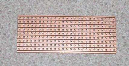
I have been building parts of the electronics myself. You can do that too. But you don’t need to if you don’t want to. Or you can choose to do something in between. Any combination of DIY and buying professional electronics exist. You may even produce your own PCBs (Printed Circuit Boards). Or you can do as I do and use strip-boards:
Most of the construction I will describe below are based on micro controllers of the PIC family. It is in principles tiny computers built as a small IC (Integrated Circuit) – also called a “chip”.
Don’t be frightened: They are really cheap and others have already written the program that shall run in the PIC.
12F629, that I use in servo decoders and signal decoders is an 8-pin IC. It is priced at about a Euro if bought in Europe. A few additional components are needed, but there is still plenty of money saved compared to buying a professional decoder for example an ESU that cost 220 kroner.
One investment is however the PIC programmer that is needed in order to transfer a program fetched somewhere on the Internet to the PIC. That is unless you buy a kit where the PIC has already been programmed. You can do so for example at litra.dk. A PIC programmer costs 275 kroner and you will also need a proper socket to hold the PIC while it is programmed. It is priced at 200 kroner at Reichelt. Both can of course be bought at a fraction of that price from aliexpress.com.
The PicKit2 software can be downloaded free of charge from Microchip, who produces the PIC micro controllers. PicKit2 is both a compiler that can translate assembler source code to HEX files (enabling changing the program code) and software that can download the HEX files to PIC controllers.
A few hand tools are necessary too.
First and foremost, a soldering station is needed. With a thermostat and a thin long-life tip. It pays to buy something really good. Such as a Weller soldering station. And remember a big roll of lead-free thin solder. Do not buy anything with lead in it. It damages your health. Our hobby should not kill us.
A desoldering pump is handy when you make mistakes or if you need to repair or dismantle. And they can be bought really cheap.
A multimeter is also a must, so that you can measure voltages and look for short circuits or missing connections. Very precise and costly models are available, but you can probably get far with a fairly cheap device.
If you love gadgets, you may get poor by buying power supplies, oscilloscopes, signal generators and so on. But you don’t really need it.
Regarding oscilloscope, I have bought a very cheap device in 2018. It has a very limited bandwidth, but is suitable for DCC signals, which are quite low frequency anyway.
 And of course, anybody will need pliers, tweezers, tiny screwdrivers and so on.
It is anybodys choice to invest in tools etc. or to buy decoders from a shop. But I cannot imagine how anybody would do without a soldering station anyway. As a minimum, a lot of wires need soldering. Of course a cheaper tool may be usable for that limited purpose.
But for me, it is a big part of the fun to build the electronics and the software.
Turnout decoder
Depending on your choice ofturnout motor type, you will need different types of decoders. At ESU (just an example – there are many other vendors), the CLACK type is called SwitchPilot and the servo type SwitchPilot servo.
But I don’t feel rich enough to pay more than 200 kroner for a decoder for 4 servos / turnouts. That is why I am building Paco’s 4-servo decoder, but with an alternative firmware, that makes it possible to adjust the end stop positions individually instead of just being able to adjust the total movement. The firmware is described and can be downloaded here. Use version 3.5.
The diagram is as follows:
 I have been buying all components at Reichelt.
A decoder looks like this (where I have only mounted two out of the four connectors for servos). The two wires that are soldered to the board connect to the command station on the normal DCC port. Soldering wires to the board is not quite as should be. It can destroy the board, if the wires a pulled. But proper connectors come at almost the same price as the rest of the board, so I have chosen to take the risk:
 If you would like to build on a proper PCB, you may find a layout at Paco’s homepage. Or the decoder can be bought as a kit or as a completed decoder at litra.dk. He has however divided the electronics in several parts – as I have also done – see below.
I have built the decoder on a stripboard as shown here:
 The red dots indicate where strips are cut. The greem dots are mounting holes where the decoder is screwed to the layout. The two green lines are connections to the command station / the tracks.
When I added turnout number 20, ECOS seized to be able to supply enough current during startup. A servo uses about 200 mA when moving. And usually only one servo at a time moves. But when ECOS is turned on, all servos are moving slightly. And that made ECOS switch off again to protect itself.
That is why I have changed my decoders to use a separate power supply. I have bought a 5V / 10A power supply from China. And I have modified the decoders by removing the power supply part:


 That requires an adapter to transform the DCC signal from +/- 17V to 0 / 5V:
 And it also requires a separate programming interface, that can be used to supply the particular decoder that is being programmed from the programming track. It is simply the components that I have removed from the decoders:
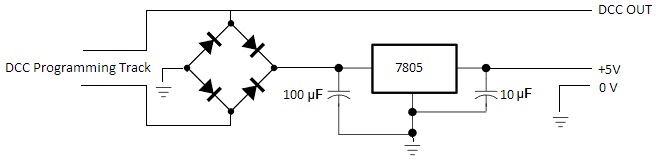
Feedback Modules
In the analog world, feedback is not needed. But in order to control model trains from a computer, the computer need to be able to keep track of where the trains are. I.e. feedback modules supply the command station and thereby the PC – or in some cases the PC directly – with that kind of information.
I have settled on S88-N modules as describe here. See the last half of that page.
Ready-made S88 modules are available from both Märklin and ESU. But they are not S88-N. S88-N are supposed to be more stable than S88. I have no personal experiences with S88 modules. But I have read abou people having problems – maybe due to long cables. ESU also have ECoSDetector modules with built-in current sensors. They fit to the ECOS, but are not S88 modules. All of them are however extremely expensive and not at all fitting my budget.
I also have no experience with ready-made S88-N modules. But I have seen that both NiceLed and nettog.dk have some from a company called Digikejs. And they are cheap enough that I might cosider them, if I had to start over. Even homemade modules are not entirely free and it easily takes an entire day to build a module with 16 current sensors and an S88-N module. So anybody must consider if it is fun to DIY or if one would rather pay a couple of hundreds of kroner extra to get some ready-made modules.
The module that I link to include current sensors. Same module also exists in a version without current sensors. And both exist in LocoNet versions instead of S88-N.
The module I have been building is inspired from the work of Sven Brandt. The HEX file can be downloadet from his website. OR you can buy the module as a kit from him.
I have bought the PCBs and the SMD components from litra.dk. He can also sell a ready-made module. Or you may go totally DIY and build the module on a strip board. He can also provide current sensors, but on a separate board.
Note that litra.dk uses S88 and not S88-N on his own layout. His S88 system includes a separate S88 interface that via an RS232 interface (which is not standard on modern PCs) connects to the PC and not the command station. That module cannot be used for S88-N.
But the S88-N-P module from Sven Brandt, that I have built in a simplified version on a strip-board as decribed here, can. The S88 connector towrds the command station can be seen to the top left and the S88-N connector towards the S88-N modules (phisically the same connector as used in EtherNet / LAN) to the lower right:

It looks as if the Digikejs modules can connect directly to the S88 port in the command station. But then I do not suppose there is any galvanic separation to protect the command station.
Sensors
The sensors are attached to the feedback modules. They sense where there are trains on the layout. My sensors are current sensors, i.e. the sense if current is flowing through a wire. But there are also other types of sensors.
As described several places on these pages, I am connecting each block to the command station via a current sensor, that is built as follows (minus the capacitor that is unnecessary if particular kinds of optocouplers are used – see below):

I have found out that the optocoupler can be protected by using a larger resistor. 20 ohm is no problem. I have also changed optocouplers from 4N25 to CNY17/IV, which have a better amplification.
I am building 16 sensors on a strip board and mounting an S88-N module to the same strip board. The picture shows my original 16-sensor board with an Uhlenbrock LocoNet feedback module:

or with an S88-N module:
 Late 2017, I have changed to a new type of sensor, where I use a different type of optocoupler as well as a bridge rectifier instead of discrete diodes:

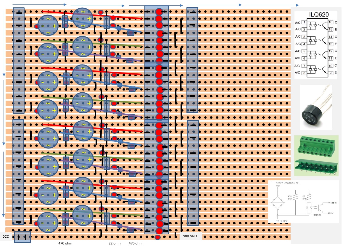 The output of current sensors based on ordinary optocouplers such as 4N25 or CNY17 is almost a square signal of 0 / 5V. And consequently, it is rather by luck if that is interpreted as a 1 by the S88 module. However, the DCC signal is not symmetric. And that can be utilized by turning the IR-diode in the optocoupler upside down corresponding to the diagram above (i.e. pin one connected to the block and pin 2 to DCC). That has proven to work. I am still using my old current sensors after having modified them as this. See my pages from medio December 2017.
ILQ620 detects current in both directions, which means the output is almost like a clean DC.
Decoder for signals
This kind of decoder can of course also be bought ready made. See for example SignalPilot from ESU. But once again, I prefer to save some money and make my own decoders.
I am using the same power supply and DCC adapter as described for the servo / turnout decoders. In fact the signal decoder hardware is almost identical to the servo decoders. Only difference is that the connecters for servos are substituted by a resistor for the LEDs in the signals. I.e. the decoders consist only of the PIC and the two resistors R1 and R2. This picture is of my first working prototype:

The firmware is different, but also from Paco. See his description here. And also see the description at litra.dk. Note that I am not using any kind of driver for the signals. I am using the PIC outputs directly. I can do that because each output only need to drive one or two LEDs. See more on my page my page about signals. Also see at the same page, how I am using three NAND gates, i.e. a chip with four NAND gates to make the two green LEDs in some signals to function correctly. For these signals, I am using one full decoder to control the four LEDs in the main signal and 1/4 of another decoder + the NAND gates to control the fifth LED.
I have been programming the prototype decoders by setting the default CV values in the source code (the ASM file) and thus generate a separate HEX file for each decoder. But since then, I have been building the programming interface described above for the servo decoders. And that interface can also be used to set CV values in signal decoders.
Signals
I have not yet built a signal for my layout. I have however been building a few prototypes. See this description.

But next time, I am going to do it better See this description. I am no longer afraid to use lacquered copper wire. It is stronger than you would think and surprisingly easy to work with.
Cabling
With two comman station, a lot of decoders for turnouts and signals, feedback modules etc. and when each decoder should be switchable between normal DCC and the programming track output – including the decoders in locomotives, cabling is not as trivial as connection the green and the red wire from the command station to the tracks.
I have a number of switches to choose what should be in normal mode and what should be in programming mode and from which of the two command stations:

As it can be seen, my first thought were that signal decoders should not be programmed at all.
With my first real layout, it was no longer feasible with a switch per decoder. Consequently, the switches were substituted by a patch panel, where I can move a connector for the decoder that should be connected to rhe programming track output of the ECOS. IB-COM programming is no longer needed, since JMRI can now also program through ECOS:

After having introduced the separate power supply and programming interface for decoders, the patch-panel is barely necessary. But I have it now, so I will keep it.