
See also the pages about the plans for the new layout:
Layout
Landscape and buildings (including semaphore signal)
Wood work, wiring, extended feedback etc.
January 23
Yeeah. Finally a parcel from NiceLED. It took “only” three weeks and one day.
Along with the servos, I have also bought a servo tester. It was somewhat expensive (80 kroner, I think). And I could have built one myself, or I could have used my ECOS and a servo decoder. I only need something to center the servos.
A servo tester can be built based on a 555 timer, that I have “in stock”:
 But it is easier just to buy one – except that I don’t have the correct connector for the battery holder. But it works:
 I have benn using two wires in the patch cable I bought for experimenting with Raspberry Pi I/O.
January 24
I have made a fine open drawer for the ECOS. I am not sure how happy I am going to be with it, since the ECOS is now very low. But when the layout is not in use, the ECOS is not in anybody’s way like this:
January 27
I have been considering how to handle the crossing in JMRI. I have made a little experiment in Panel Editor, where I simply has been drawing the crossing as two track pieces representing the same OBlock and drawn as a cross: The signal is controlled by Signal Mast logic. And in my experiment I have set the rules so that the “approach-block” must be occupied and the two crossing blocks must be free in order to get green light. It works – at least in the simulator:
 The mast shall of course not be both source and destination. But it was only a quick experiment.
The crossing actually consists of two pieces of track without electrical connection to each other. I have thought of using that fact to have a sensor for each direction and then add some logix in JMRI to implement an emergency stop if both tracks are becoming occupied. I hope that could prohibit train crashes.
It does not seem that one can turn the layout off from Logix. But it is possible to execute a Jython script. And it is possible to switch all track power off from Jython. See https://github.com/JMRI/JMRI/blob/master/jython/AutoLayoutPowerOff.py
The entire crossing need to be one block, though. Otherwise, two warrants could allocate the crossing at the same time and trains would potentially collide.
The split into blocks is as a whole being considered, so that I can begin laying tracks: The signals on the drawing are the logical or virtual signals – those to be used by JMRI to make Warrants work. The relatively few physical signals to be placed on the real layout will only be on the visible part of the layout and not all the virtual signals will be represented by physical ones. Some physical signals may even not correspond to a virtual signal. For example there shall be only one entry signal to Skive H from left to right even though there are two logical signals – one for each track.
January 29
I have started all sorts of small tasks. Right now I am preparing to mount the wiring. I wish I had bought connector strips like these for my current sensors: They would make it much easier to disassemble and reassemble if a module has to be taken out for repair. But no need for wining. I will just make some myself by cutting copper wire from installation cable into tiny pieces:
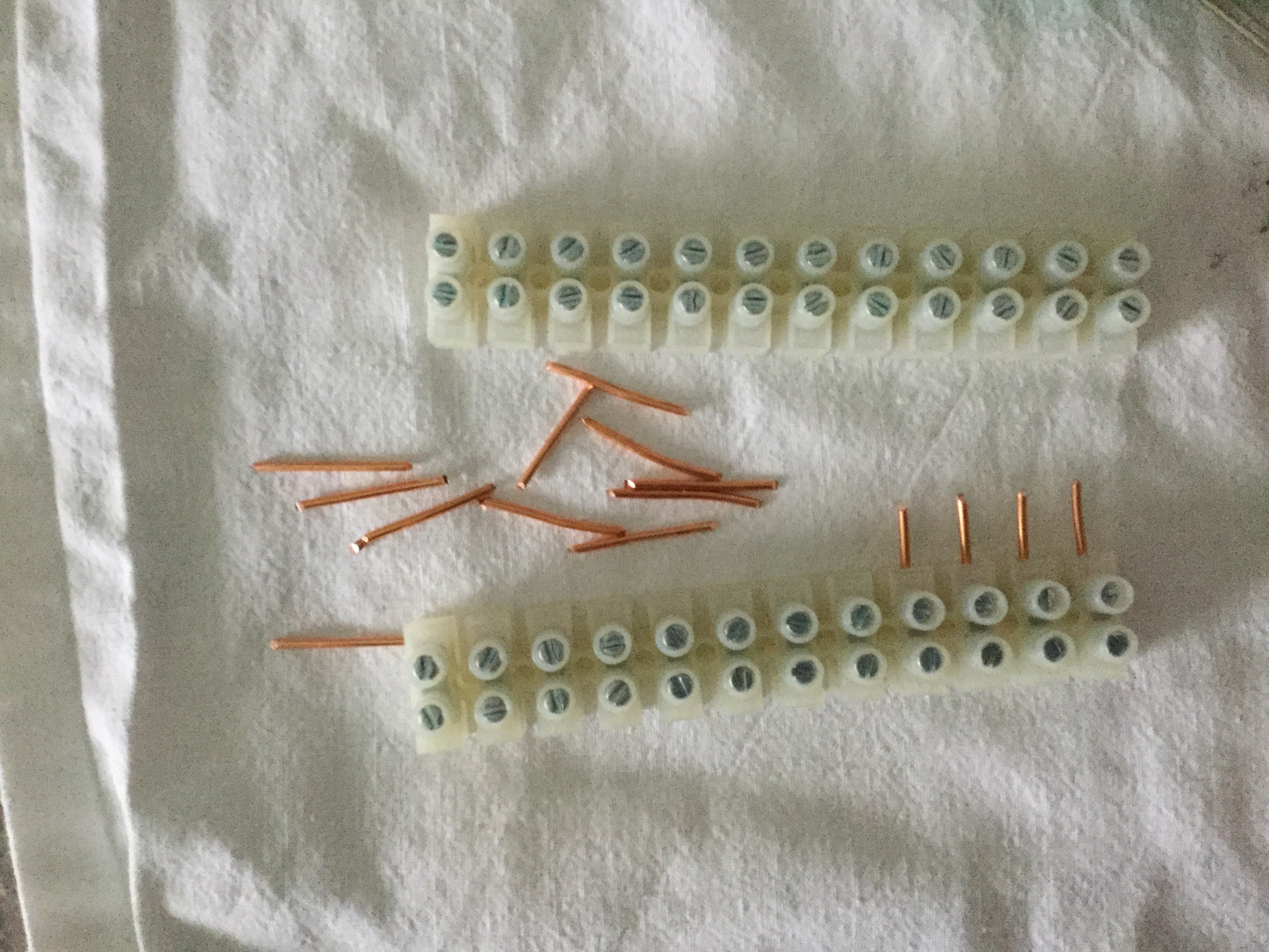 And then I have begun the noise dampening.I am almost done with the lower level. Only the front corners and the flex track are still missing:
 I am gluing the green stuff with wood glue. I have bought a liter. I am trying to use only a very thin layer, but I am still using quite a bit of glue.
January 30
I have started to define the layout in JMRI. I have chosen to use LocoNet Simulator instead of ECOS. That way I can define the entire layout and test signalling without even connecting to the ECOS. It is true that I then have to do “global-search-and-replace” on all sensors when I will start using JMRI with my physical layout. But I have tried that operation before when I replaced IB-COM with ECOS.
Until further, I have defined all Sensors, Turnouts, OBlocks, Portals and Paths. I have done so directly in the tables in JMRI. That is easy. Easier than doing it through tiny dialog boxes in Panel Editor But now comes the hard part, i.e drawing the layout in Panel Editor. I will not – at least initially – draw the layout in Layout Editor too: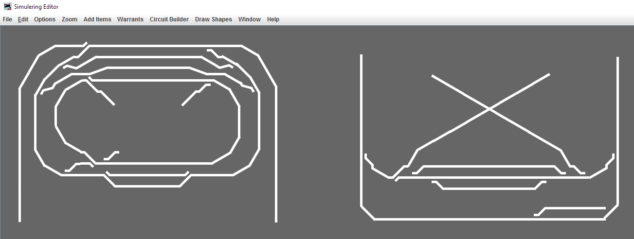 The tricky part is that there are several icon sets to choose from and not least that Panel Editor is not absolutely flawless. Special attention has to be given to the fact that even though one chooses a turnout and a set of paths in the “insert” dialog, one shall not count on getting what one asks for. One has to right-click several times on each icon and choose “edit” to make the icon represent what it is supposed to. Of course that is an error in Panel Editor. And of course the error can be corrected. But somebody else need to do that.
February 4
Now that the Saturday cleaning is over and done with, it is the time to build servos into the turnouts. I will only make the turnouts that I need right now.
For the purpose, I have sawed tiny pieces of 4 mm acrylic / plexiglass. Two pieces per servo – one 25×28 mm to mount the servo and one 28×10 mm to hold the piano wire into place.
Once more, I have tried using a jigsaw to cut the plexiglass. It doesn’t work. The blade becomes so hot that it melts the plexiglass. And thereby the plexiglass glues itself together again right behind the saw blade. So I am using a manual saw instead. It is not getting pretty. But that doesn’t matter. Everything is hidden underneath the turnouts.
In addition, I have been cutting the servo horns to length, so that there is room for them inside the turnouts. In addition, I have lined up double adhesive tape etc.: Ét voila:
 I have finalized the noise dampening on the lower level. Tomorrow, I will be laying the track including sawing holes in the plywood underneath the turnouts to make room for servos.
Then plywood for Skive H need to be sawed and mounted using threaded rods. And then comes wiring and electronics.
February 5
I have spent most of the day sawing holes for servos and finding the right track pieces so that isolation between blocks is according to plan. In addition, one of the old turnouts had to have it’s 1 mm piano wire exchanged with 0,6 mm.
But now the first oval is in place: I have spent the last hour of the day soldering the final 6 current sensors for S88-N module #2, which until now onla had 10 current sensors.
February 6
Wiring for the 6 new current sensors is done. Now I only need to test the entire module. But that will have to wait a little.
February 7
I have added blocks 27 and 28 to JMRI according to the track plan above (January 27). It was not easy. There seems to be an error in JMRI Panel Editor so that one cannot create an OBlock without ensuring that the entire layout is interlinked with Portals and Paths.
Or rather: The problem is the exact opposite. One is allowed to save a layout without this coherency. But when the file is loaded during JMRI startup one gets a very long and cryptic error message and no part of the file can be read. I.e. the entire layout is lost.
Luckily JMRI stores a series of backups of the layout file. So I could copy one of these backups and then try again. I managed to get through in the third attempt.
Apart from that, I have started a small series production of 4-servo / turnout decoders:
February 8
I have defined all signal masts as virtual in JMRI. And I have placed the first few in the panel and defined signal mast logic for those.
I will not be coming to the physical signals until a later stage.Right now the only purpose with signals is that SCWarrants need to have signals to run trains.
Work on the servo decoders is progressing.
February 9
All signals are placed on the layout in JMRI. In addition I have been adding block numbers and turnout numbers so that they are visible. Only a small portion of the signal logic is defined.
I have discovered that the guy who originally made Warrants in JMRI has removed my SCWarrants. To say it in the nicest way possible, I am less than satisfied with that. But it looks as if he has been making the original Warrants signal aware, so a test must reveal if I should be happy or mad/sad, i.e. if I have to start over again to make Warrants work on my layout. I have a hunch that at least the functionality with not having to record throttle commands is missing.
It is going forward with the servo decoders. I still haven’t mounted any active components or programmed any micro controllers:
February 11
The last few components are now soldered. Only micro controller programming and wiring is left. But that is going to wait until I have added a board for all the electronics.
In the meantime I have sawed the plywood for Skive H. I just need to glue and screw the three pieces together:
February 12
I was in Bauhaus to buy a few 3×13 mm screws etc. Thereby I can assemble the plywood for Skive H.
Besides, I have at long last added the board for electronics in term of the leftovers of the 9 mm plywood board. I will have to see if it is too thin to screw the electronics into place. But now it is there and I have moved the layout back to the corner where it belongs: In addition, I have been working with a hole saw tomake holes in the baseboard for wiring back and forth between ECOS and the electronics board (or between the front and the back of the layout). And then I have been putting a power rail on the baseboard.
I am considering if I should buy something like this https://www.elvvs.dk/c/ledningskanal-m-slids-3393/ or if I should glue wires to the baseboard, continue with the hooks I used on the prototype or what.
At least, it is not going to be allowed to become a spider web of wires like the prototype.
Late in the evening, I finally found the solution and has now ordered cable binders and a roll of Velcro from AV-CABLES. The plan is to attach all wiring with Velcro. The cable binders is for attaching the electronics thatcannot be screwed. For example the power supply for ECOS.