See also the pages about the plans for the new layout:
Layout
Landscape and buildings (including semaphore signal)
Wood work, wiring, extended feedback etc.
March 21
Great idea about using straws to make sure wiring from an upper level do not interfere with trains running underneath: http://www.niels-modeltog.dk/index.php?option=com_content&view=article&id=53:det-ny-svenstrup-h-del-3&catid=5:anlaegsbygning&Itemid=8
And then I have been sawing plexiglass pieces for the next ten turnouts. I managed to use an electrical jigsaw this time. By running it very slowly, by using a fine-toothed blade (meant for sawing in metal) and by attaching a piece of paper-tape where I am sawing, I managed not to melt the plexiglass:
March 23
I am lining up to the next turnouts. And I can see that I probably do not have enough 0,6 mm piano wire. I do however have 2 meters of 0,5 mm wire. So I will have to see if that works or if it is too soft.
And I already forgot how much I was cutting away from the servo horns last time. But luckily, I can just take a picture. The piano wire is in hole 2. The cut is after hole 3: I managed to unpack 10 servos and cut the servo horns to size. Do you know how long time it takes just to pull the servos out of their plastic bags? Answer: Surprisingly long.
March 24 and 25
I only have left to assemble two out of ten turnouts. And to add lanters to the 4 of these that will remain visible.
But now I have neither anymore 0,6 mm piano wire nor any double-sided tape left. I have already assembled one turnout using 0,5 mm wire. It works OK. And I have been to Bauhaus to buy more double-sided tape. It looks like this and is called “ultra strong”:

With this, the last two turnouts have been assembled, so now I have to mark and saw holes for all ten. Since some of the holes are going to be very close to the edge of the tracé, I will have to device some means of enforcing the the tracé. Here is how the markings look like:


It was a really good idea to cut the holes in paper first. A couple of them got wrong, which could be remedied in the paper, but might have ruinex the plywood completely.
March 27
For once, I managed to spend a couple of hours on a normal weekdays evening to saw holes for the new turnouts:
Next steps will be mounting lanterns in the visible turnouts, tracklaying and wiring as well as adjustment of height and slope including supporting the curved parts of the new track.
March 28
I have mounted lanterns in all the visible turnouts. And then I have begun to lay the puzzle that it is to re-use as many of the existing track pieces as possible – including the ones that I have made into isolating tracks by breaking off the contacts in one end.
March 29
I had no energy for modelling today. But I did a bit of detailed design:
About a week ago, I wrote that I had seen niels-modeltog.dk use straws to guide wires underneath the track, so that trains passing underneath would not be bothered by those wires. I still think that is a good idea. OR one could fix the wires using a hot glue gun.
But anyway, I have figured out that since I have bought plenty of velcro tape, I will be stapling a few stripes of velcro underneath the track instead. By that, I am going to get a more flexible solution, where it is also possible to fix the wires for my servos. The connectors would not be able to pass through a straw.
The problem is however that by now, I am perfectly able to fix wires for track and turnouts. But I do not yet know where I am going to put signals and other stuff.
That is why I am considering not to glue the board, but only fix it by a screw in each side – apart from the threaded rods at the front.
But should I also make sure that only a single connector is used to connect all wiring to the board? Naaaarh:
The turnouts are controlled by two decoders for the five turnouts at Skive H and two additional decoders for the eight turnouts at the rear shadow yard, out of which only half are in the detachable board. And each of these decoders must have a connector to connect it to the patch panel anyway. Regarding the turnouts at the rear shadow yard that are connected to a decoder on a different board, they already have a connector too.
So only the track is left. The programming track must also be connected to the patch panel, and therefore equipped with a connector. And I could connect the rest of the track via a small row of cable joints. Thereby, I will be able to dis-mount the board fairly easily, i.e. by disconnecting the cable joints and less than 10 connectors. Remember that it is not supposed to be an everyday operation.
March 30
I have filled Skive H with velcro underneath:
April 1
I have strated laying track at Skive H and the rear shadow yard:

This time, I am using a lot of the small red hyper-expensive (15 kroner for 8, i.e. for 4 joints) plastic things for isolating adjacent blocks of track from one another.
I have previously been bithing that they do not work properly and that it is a lot easier, cheaper and better to simply break off the contact from one piece of track.
But right now, there are many places on my layout, where I would have to be violent against track and turnouts costing a bit too much and that would become harder to re-use later on when I am making my next layout.
And in fact, I have found a fairly good way to mount the plastic things without destroying them. The secret seem to be not to try to mount them on brand new track. I.e. Put the track together and then tear it apart again. Then the contacts seem to be pressed together just enough to be able to mount the plastic thing.
April 2
I have instaled all the Märklin tracks and connected them except for a single turnout. In addition, I have made supports for the upper board in both sides. It lifts the board just enough that a Lima B-car can sneak itself around on its way to and from the lower shadow yard without scraping the upper level, even though the track is closer than they should be. It is recommendable to not ignore the minimum distance between tracks as proposed by Märklin:
Naturally, it took some time. But the only thing tat did not work right away was one of the servo/turnout decoders, which seemed unstable, i.e. all 4 servos kept moving in a seemingly random pattern. I don´t know what the exact problem was, but I tried to re-program the PIC without any effect. Then I rplaced it with a new PIC. And now the decoder works.
The next exiting mini-project is going to be the two pieces of flex track that will complete the lower level.
I have considered if it is worth fooling around with the flex track. The gap can be easily closed with Märklin track: But this would not fit the woodwork that I have already made. And the very tight curves to both sides is the same as begging for trouble. Finally, it would not leave much space to stick my head up underneath the layout and remedy when trains are de-railed. So I will stick to the idea with flex track.
April 3
As preparation for laying the flex track, I need to add an extra layer of 6 mm mdf to make up for the plastic-ballast, that raises the Märklin track 6 mm. I have been cutting some of the mdf, made paper templates for the rest and removed the noise damping material from the area: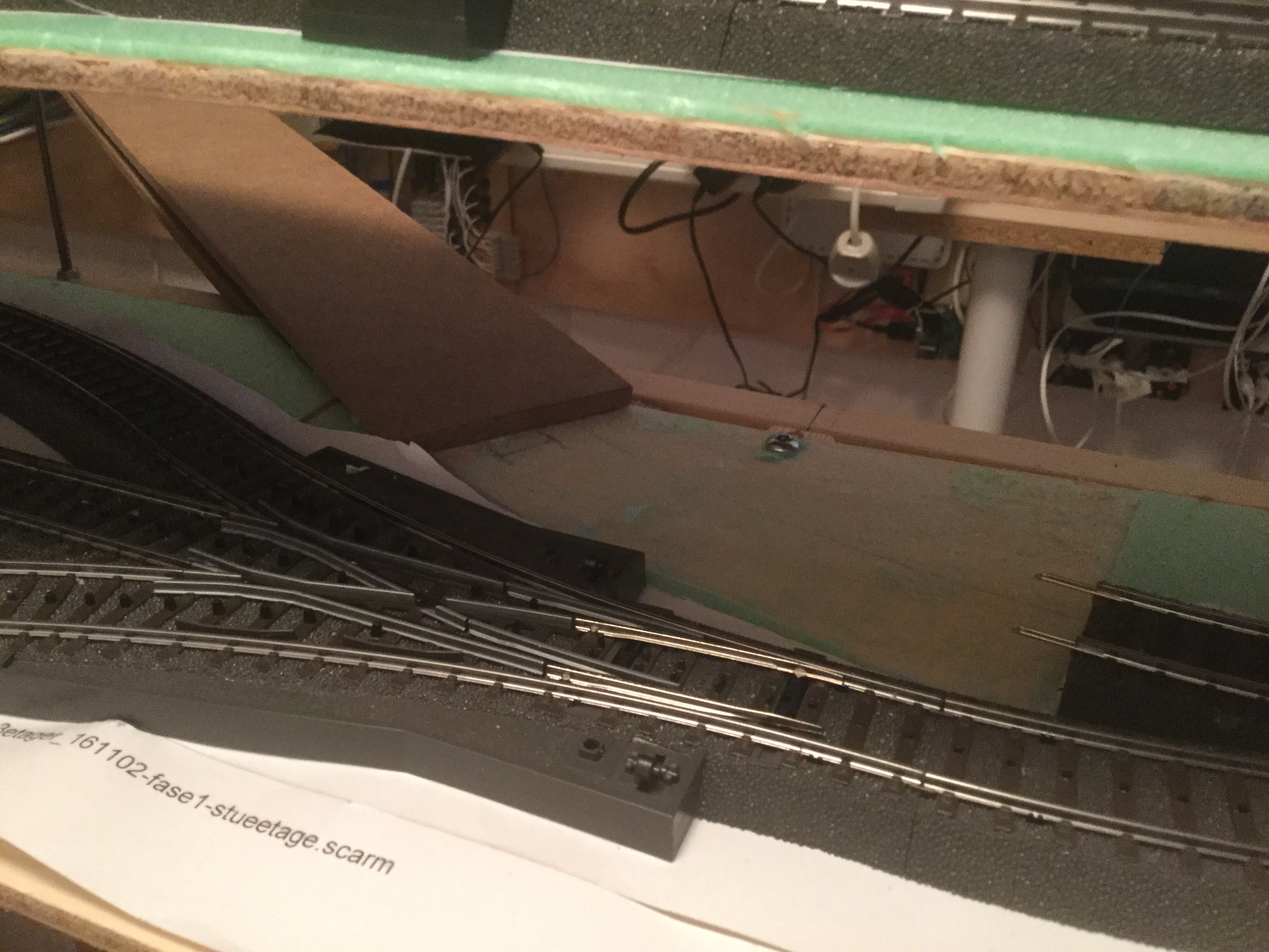
April 4
I have been cutting according to the paper templates. I have also been glueing the first side, i.e. the extra layer of mdf is glued on top of the existing layer. It is so thin that I do not have short enough screws to screw it together, so I hope that the glue is enough:
Also, I do not have enough clamps, so I will glue the other side tomorrow.
April 7
Ready to lay the flex track:
I thought I should use copper wire from a piece of installation cable (1,5 mm2, i.e. 1,4 mm in diameter) as the center conductor, but it is too stiff. Instead, I have bought som silvered copper wire from Panduro Hobby. They have different thiknesses. I have chosen 0,8 mm.
Now I wish that jornebanen.dk, where I got the inspiration, had been writing a few details about how he did. Which kind of wire? One long piece or many shorter? What does the rear look like?
April 8
Here is my method:
With regular intervals, there is a small hole in the middle of a sleeper. The holes are probably meant to fix the track using small nails. But I am using them to put the copper wire through. I am cutting a piece of wire long enough to use from one hole to the next.
In the track end nearest to the front shadow yard, I have just bent the wire piece around the sleepers and then soldered them together on the rear of the track. In addition, I have soldered a small piece of wire to the last of these wire pieces:

The rest is done similarly, only that the wire is going through holes in the MDF board underneath. And I am soldering on the underside of the MDF:

Übung macht der meister, as the Germans say. The first piece of track took a long time to solder, because I had been bending each piece of wire around in a circle, so that it could be soldered to itself at the rear. But that is not what is is all about. Instead I made the pieces a bit shorter on the next piece of track and bent them all in the same direction, so that they were in parallel and ready to be soldered to be soldered together with the next piece:
About the Peco flex track: I can hear an immediate difference in the sound it makes, whwn a train is running on the Peco track compared to the Märklin track. The Peco track is a lot less noisy. I don’t know why. I can think of a few differences:
The Peco track is without the big plastic footing that firmly connects all the Märklin track together and might provide resonance. I could try to either glue the Märklin track to fix it to the board (right now, it is just lying loose without screws or anything), or I could try to make some resonance damping. I have some heavy asphalt-like self-adhesive stuff in big sizes meant to soften resonance in cars, which I could cut into tiny bits and put underneath the track.
The 3rd rail consist of small studs on the Märklin track, whereas it consists of my longer pieces of wire on the Peco. It might mean that the locomotive simply emits less noise from the 3rd rail shoe. This could be determined by experiment, since Peco actually produces a 3rd rail (item number SL-17), that I could buy and install. But I would like to improve my Märklin track and not make my Peco track worse.