2017 part 6 – Summertime – With Some Train Time Now And Then

April 23

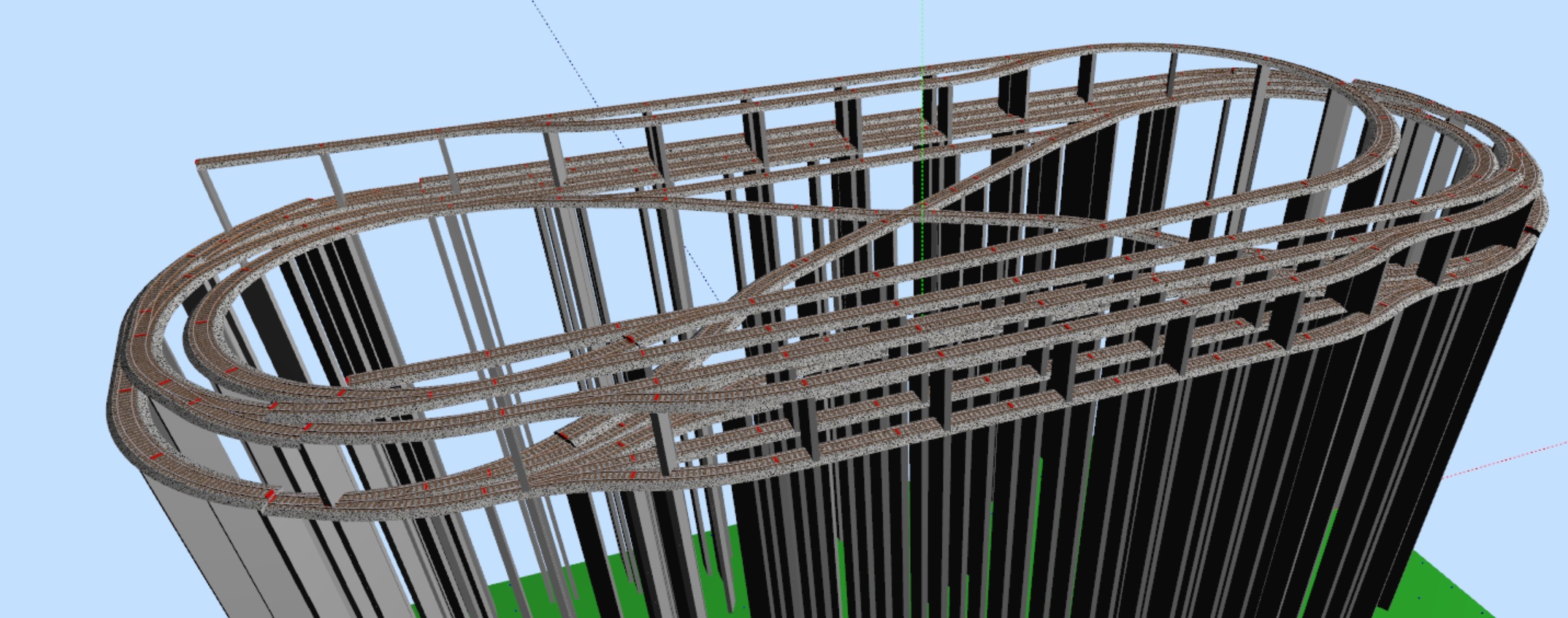
3etager_fase1_170201

Houston, we have a problem: See my division into blocks:A typical pattern would be that a train A is positioned in block 21. A is planned for departure “downstairs” via blocks 23, 11, 12 etc.. In addition another train B has stopped with it’s front in block 26 and it’s rear in block 11 and is on it’s way into block 21, but cannot go further due to signal 26-21 showing “stop”.

What will then happen is that train A proceeds past signal 21-23, which shows “proceed”, when it’s warrant become active, but stops as soon as the front of the train is inside block 23 (still with the rear of the train in block 21, so that signal 26-21 shows “stop” and holds train B back), because signal 23-11 shows “stop”. This establishes a deadlock since the two trains are waiting for each other.

The circle is not big enough. I need more blocks and signals. The question is how?

Block 23 and 26 can be split in the middle, i.e. at the edge of turnouts T11 and T15. That will make both trains move a little further. But not enough to get the rear ends out of blocks 11 and 21.

Block 21 can be split in the middle. That might just do the last bit. But it will not look very nice to have train halfway at the platform stopping for an invisible virtual signal. So it will be block 11 that is being split into more than one block. I can do it in the middle and probably solve most cases.

But I can also split it into 3 blocks, so that the middle block consists of 6 track pieces (corresponding to my maximum train length) and so that the turnout + 1 track piece in each end form the other two blocks. I suppose this will give better flexibility, since a waiting train will get fully into block 11.

The target is to be able to run 3 trains simultaneously. I.e. two trains must be able to be waiting to enter the station without blocking the train at the station from leaving.

image

Ultimately each and every piece of track could be it’s own block. But it must be sufficient if the circle is divided into blocks so that every second block is 6 track pieces long and the other quite short:I.e. I will be needing 5 additional sensors. And I haven’t got 5 free sensors. I only have 4. There is probably no benefit in splitting block 23 as indicated. So I can save the 5th sensor right there.

image
image
image
image
3etager_fase1_170425

On the following pictures, the liquorice bits are illustrating the front of three trains. Train A is in block 21, trains B and C are waiting to enter block 21:When train A is started, it has permission to go as far as the block before train C:Then train B can move into block 21 and train C can move forward to wait at the next waiting position:Finally, train A can move on. Either in the back of the queue for block 21 or more likely away via block 12:For this reason, my layout is going to be changes like this:

April 26

I did some measurements on current sensor 32 (the one that has never worked). The S88-N module works OK. But there might be something wrong with the diodes. Either one of them is turned the wrong way around or one is defect. I need to take the entire module out for repairs, if I must use number 32 at some point in time.

April 29

I got the extra blocks defined today. It was quite fast to do the physical part with isolating track and soldering wires.

But the JMRI setup turned out to take longer time. Even though the most annoying errors in the editor seem to have been corrected by somebody, but it took me 3 – 4 hours to re-define a good part of the layout.

And now it seems the there is no more frost at night. That means cleaning and preparing the green house and planting tomatoes tomorrow. And not much model railroading until autumn.

May 9

Even though it is spring, I did a railrod-thing today. I have been at Togdillen to collect my Heljan IC3 train. It has been there for repairs – or rather finalization on behalf of Heljan.

The specific problem was that the drive shafts, which from Heljan’s hands are made of plastic, kept falling off or falling apart. But now Togdillen have replaced them with metal drive shafts.

Until further, it looks good. The train has been running several rounds on my layout without blowing itself up.

The train is a bit noisy. For one thing the collector shoe “talks” somewhat loud and for another, the new drive shafts are not exactly silent either. But it runs. And to be fair, the noise is not much worse than what could as well come from a Märklin locomotive.

May 13

Instead of pulling weeds from the garden, I experimented with automatic train driving.

It works pretty well as long as I only run locomotives without wagons. But I have one train with wagons. And even though the rear wagon is equipped with a collector shoe and actually draws current, it happens quite often that other trains are permitted to move and thereby crash with this one.

I have tried debugging the problem. And it looks very much as if it is not reliable enough with a single collector shoe that is not even placed at the rear boogie.

Another problem is that as trains are constantly waiting for each other, they move in an unrealistic pattern with way to much starting and stopping.

The question is if I really want several trains to run behind each other? Maybe I should only run one train at a time?

On the other hand, it looks good if – just occasionally – two trains could enter Skive H simultaneously (of course from each direction and to each their own platform).

Maybe I should – instead of having SCWarrants carefully trying to free blocks up for subsequent trains – change it so that a train does not start unless the entire route can be allocated and before all turnouts are set? That also means that if just one block is occupied, no part of the route may be allocated. And blocks may not be de-allocated one at a time, but have to be de-allocated in one bulk operation when the train has moved fully into the final destination bLock and the warrant is finalized.

Thinking about it, it may be enough to do the last bit, i.e. de-allocate in a bulk operation. That change can be made by just deleting a single line of code. So I will try it out first.

May 29

The weather was no good, so I managed to implement the bulk allocation and deallocation of SCWarrant routes.

At the same time, I also made sure that all turnouts are set before the train starts to move.

It makes the layout less lively, but it is more realistic that having trains queing up behind each other.

It works great. No more collisions.

I did try the easy fix with only bulk de-allocation. But it didn’t work. Deadlock situations occurred very fast.

June 11

The weather is nice and warm, and I am mostly outside enjoying it. But I could not completely stay away from the railroad. I had to see if I can still run several trains simultaneously.

And to upper the odds a bit, I was putting some Lima B wagons behind to locomotives and ran my Roco train as the third train. JMRI and warrant-wise, it works fine. But the Lima wagons are not 100% reliable. At one time I had a bad derailment accident. And a couple of times wagons decoupled. All in all good. But I need som better (and nicer looking) wagons.

An other irritating issue that I did a little to cope with: Since it takes a while to move a turnout (I have programmed the ECOS to wait 2,5 seconds), since the ECOS only seem to move one turnout at a time and since JMRI/Warrants seems to sometimes set all turnouts along the route twice, it takes some time before a train starts moving. I tampered a bit with the ECOS turnout code inside JMRI, so that if a turnout is already set in its wanted position (JMRI knows very well the position of all turnouts), no command is sent to ECOS. That helped a lot. But I will leave it as prototype code until further.

I also ran my newly renovated Heljan IC3 train. It actually runs pretty stable. It looks as if it can pass the curved R1 turnouts without problems. It gous uphill, downhill, around in narrow curves. But but but. It derails if it shall leave the main track through a “normal” 24611 or 24612 turnout, which is supposed to be R2, but where on my layout the train must continue through an S-curve, which is also R2. I will have to define Warrants for the IC3 train without such S-curves.

Apart from that I have not touched the train since my latest update. I am growing tomatoes etc. And I have been playing with home automation in Domoticz. Se separate page.

2017 part 5 – Building New Layout – JMRI Setup & Various Adjustments

April 9

I was at the DMJU (Danish Model Railway Union) exibition in Køge. Many interesting things. But to be honest, I was somewhat disappointed by the quality and level of detail in the club layouts that exibited. But in hinsight, it is only people making it for fun and not to impress others. If that is what one wants, then go to Hamburg and see Miniatür Wunderland.

At the exibition, I noted these things:

Mck exibited red Bn cars, that I got the impression are on their way from the factory in China. In addition, they had a raw and unpainted Bns (i.e. cab car), where one could see a bit about how the light functions are going to work. He told that Mck is going to put a light-kit including a 3rd-rail shoe on the market – maybe this autumn, and that the same thing will be built into the Bns from the beginning.

In addition, they had an early version of the Q-steam-locomotive running. Many people were taking photographs of the nice little thing, even though he underlined that it was indeed a very early prototype – possible with a lot of faults.

Finally, he had an MR/MRD train-set. It was in a wrong color and with wrong LEDs. But no matter that, it absolutely outshined the Lima model that I re-built a few months ago.

Märklin C-track does not have to be noisy. There were plenty of C-track layouts – including one at Märklin’s own exibition, that did not emit much noise. And they were just loose track on top of an MDF board. Maybe because it was in a big room with a lot of noise around? Or maybe because they were using different locomotives? Or maybe I just need to determine what is wrong on my layout?

http://www.mollehem.se/ has some nice Dansih and Swedish signals. He has been smart enough to produce the entire signal – head, mast (which is very thin as it should be) and foot as one PCB. The head is equipped with a pice of plastik at the front that looks like a correct signal to me and another piece of plastik at the rear, that is better described as just a piece of plastik with much resemblence with reality. The mast does not look much like the real mast either, but all in all, it is a nice signal.

For 50 kroner, he also sells servos with a little piece of plastic, that makes them ideal to use with any turnout brand. Finally he sells servo decoders and other kinds of electronics.

Togdillen Was also present with – among other items – IC3 train-sets built from spareparts from Heljan. I asked if they could run and told him about my IC3 train, that I bought from him. He said that I should come to them if it falls apart again, and they will fix it so that it lasts. They want satisfied customers.

Just before bedtime, I managed to edit the XML file into which I some time ago has been defining my new layout. The editing was about replacing the syntax of sensor names from Loconet simulator syntax to ECOS syntax.

April 10

I expected some trouble in getting the layout XML file including its built-in signal logic etc. to work.

But no – no problems at all. It worked right away.

I did however have a few problems in getting Warrants and my Jython scripts to work:

1. One problem was in SCWarrants, that was a bit too eager deallocating blocks to avoid one warrant from prohibit another to run. So eager that the block that was just entered sometimes was deallocated, with the result that the train could stop in the middle of its route.

2. I had to set debounce timers for all ECOS sensors. I have chosen 25 ms delay when a sensor becomes active and 100 ms when it deactivates. There has to be some difference, to avoid problems with a sensor for the block that is left becomes inactive before the sensor for the block that is entered becomes active, thus leading to the detection of a lost train.

3. The function that I made in JMRI for letting a Jython script wait for a warrant to enter a new block did not work correctly every time when a warrant terminated funktion.

I have fixed these minor issues and re-implemented my Jython script for one of my trains, defined buttons to start and stop my trains as well as information fields for the running trains, created SCWarrants for the one train – and spent all day doing so.

And the JMRI fixes are naturally pushed to Github so that they will be part of the next JMRI release.

And now the first train is running pretty stable. The train consists of an old Märklin Santa Fe (3060 for conisseurs) locomotive with the engine rebuilt as a 5-pole DC engine and equipped with an ESU decoder, as well as 3 well-used Lime B-cars. I have uploaded a video here.

A few accidents are happening every now and then, such as a railway car derailing or just decoupling. Or on rare occasions, a sensor is not detected correctly. And then “funny” things obviously happens. But I think the software is as stable as it is ever going to be. Probably, only some kind of duplicated sensor system can really make things more stable.

I can foresee one thing, I need to do pretty soon, if I want to run more trains simultaneously, which I do: I need to make sure that the rear of a train is detectable, i.e. Is equipped with a 3rd-rail shoe so that it draws current. As it is now, JMRI cannot detect the rear of my rather long train, and thereby deallocates a block too soon, making it available for another train to enter. I will probably be saved by the signalling system, since the next train entering the freed block will be given a stop aspect, which JMRI will react upon, but it is not safe.

April 11

One of my turnouts needed adjustment, since the servo was “singing” in one of the positions. This was easy enough, since it was just a matter of changing the CV value in the decoder that controls that particular servo in that particular position.

image

Another turnout was a bit more challenging. It was one of my 3-way turnouts:

It operates as two independent turnouts. But mechanically, they are not independent, since one of the moving parts is pushing on the other moving part as can be seen on the picture. Again referring to the picture, the outer turnout is closed and the inner is thrown. That is OK. But if I now also throws the outer turnout, the inner turnout is pushing enough on the outer that it does not shift properly, so that trains will de-rail. I tried adjusting CV value the best I could. But it was not enough. I also tried bending the outer turnout slightly, but that was not enough either.

I assume that if one uses Märklins own special decoder (74465), it will not be possible to have both turnouts trown simultaneusly. I have made the same thing using Logix in JMRI. The logix I have made reacts upon the outer turnout being thrown. And the action it takes is to close the inner turnout. Simple and effective. While I was at it, I made the same logix for my other 3-way turnout.

A bit of research shows that it is not the Märklin 74465 decoder, that makes the 3-way turnout function as one turnout. That is a function in the ECOS, which is able to utilize two consequtive turnout adresses combined, if one uses the 3-way turnout icon.

But I cannot use that function in the ECOS, since JMRI does not know anything about 3-way turnouts. In JMRI, one needs to draw and control the two integrated turnouts individually. I.e. My solution with logix seems to be the right one for me.

April 15

I defined warrants for a couple of trains more. But that lead to the greatest of disasters with all cars derailing and crashing deep into a ravine. I have to make my whole train detectable, which means equipping the rear bogie with a 3rd-rail shoe and some current consumption.

Until further, I will just run locomotives without cars. But that is going to become a bit dull.

April 17

It has become spring-time. The driveway is high-pressure cleaned. But I have also been driving trains via SCWarrants.

It was an occasion for a few improvements to SCWarrants (that are not yet pushed to JMRI):

1. I have removed the function that was meant to de-allocate blocks further along the route, if they are occupied by another train. First, it should not be necessary. And second, it has happened on more than one occasion that the function was executed at the same moment as the train was entering the next block, which meant that the block was being de-allocated and occupied by the train at the same time. And thereby the train stopped.

2. Until now, the first allocation of blocks was done in the normal Warrant code, which meant that all blocks were allocated no matter if they are occupied or not. That did not work – especially not now that occupied blocks are no longer de-allocated. The problem is that if one warrant has allocated the block, an other warrant that is supposed to move the train away from that block cannot do so, since it cannot allocate the block that is already allocated to the first warrant. So I have now implemented a very simplified version of this initial allocation: it only allocates the start block.

In addition, I have been fiddling a bit more with debounce timers, because my sensor 17 seems a bit unstable – probably due to dirty track. I have in general increased the timers from 25 / 100 ms to 50 / 200 ms. And for sensor 17, I have set them to 100 / 500 ms.

In addition, I have defined (virtual) signal masts at the entrance to all side-tracks.

April 18

More high pressure cleaning – this time the terrasse.

But I have also made a couple of software improvements:

1. My script to run trains by warrants had the flaw that it re-used the throttle from the warrant itself. This meant that when the last warrant had finished and thereby the throttle had gone, the script failed to turn of lights etc. On the locomotive.

2. SCWarrants will now slow down in the block before the destination block.

3. It can happen that two events are received to tell that the destination block is becoming free. And in that case, a race condition leading to a null pointer exception could occur. That made a thread in the program die. Such behaviour is seldom healthy for a program.

4. If the train doesn’t move (speed == 0), the warrant no longer reacts if the block ahead becomes occupied. It might have been in combination with one of the things, I have corrected, but I had an incident, where my old Santa Fe was yelding nicely to wait for another train that should pass in the crossing in the middle of my layout. But as soon as the other train had finished occupying the crossing, i.e. when the locomotive but not all wagons had passed the crossing, Sant Fe speeded ahead with the result that the two trains crashed and the offended train was damaged. Not good! It must be beacuse the Santa Fe warrant thought that since the crossing was it’s next block, it must have been Santa Fe that entered it. I just don’t understand why I have been unable to provoke the same error again.

5. I have increased the time configured in ECOS to set a turnout. Until now, all turnouts have only had 250 ms to move. I have increased that to 2500 ms or 2,5 seconds. It fits pretty well to the time it actually takes for a servo to move a turnout. And it is the maximum in ECOS.

image

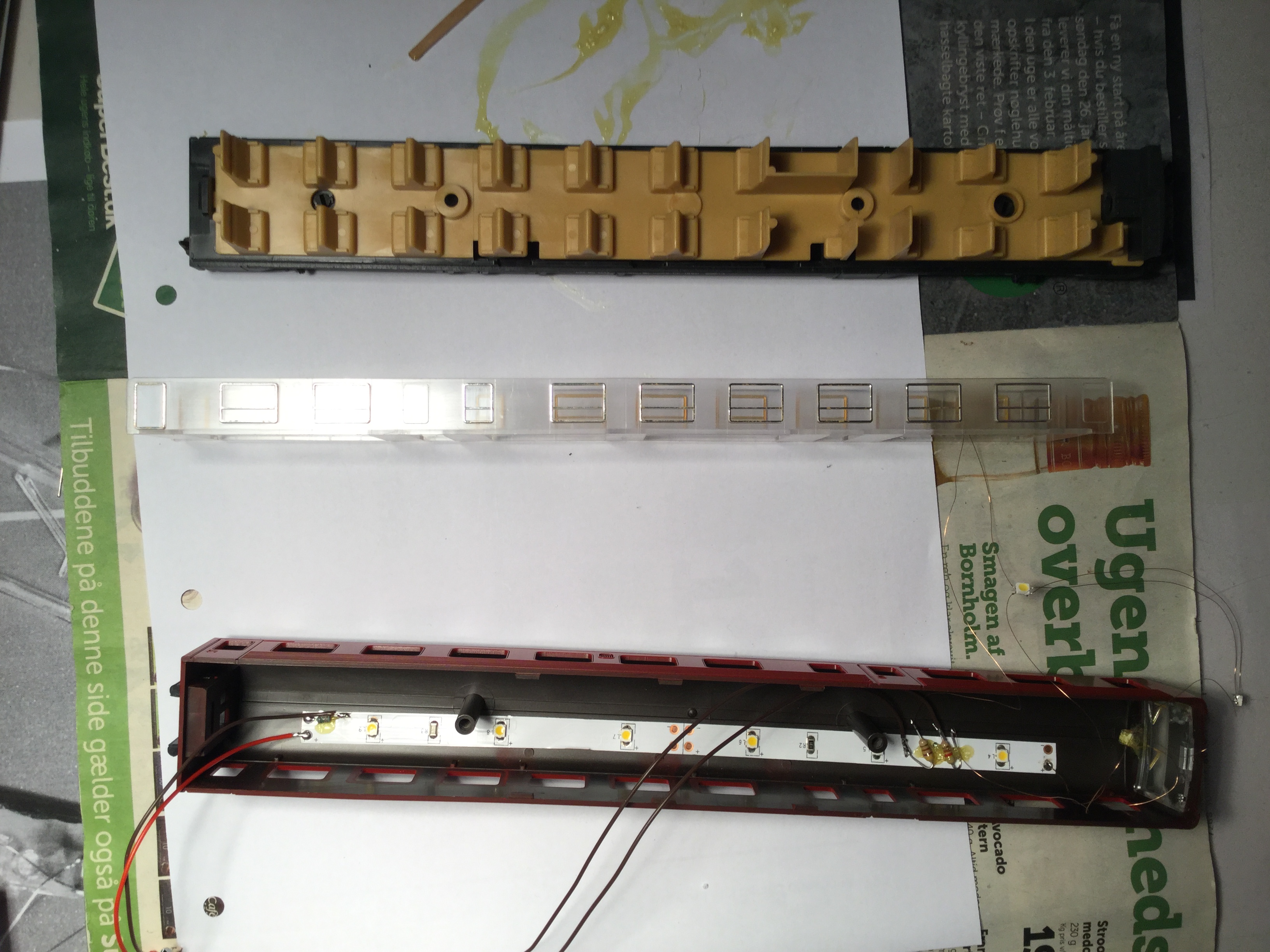
Besides, I have at long last found out how to disassemble a Lima B wagon. I have “asked” Google numerous times without success. But by squeezing my ugliest Lima wagon carefully, I found out: Roof and windows are casted into one piece. And the sides and bottom in an other piece. So by gently pressing the winws inward, wriggle a bit and so on, it is possible to pull the two parts apart. Use only your fingers. No tools:

This finding could enable me to add interior lights and collector shoe.

April 19

More JMRI improvements:

1. Messages are shown in the window containing the list of warrants when the train runs. I have made these messages specific and relevant for SCWarrants.

2. Editing TimeToPlatform now actually works.

I Have pushed these and previous improvements to Github so that they will become part of the next JMRI release.

April 22

I tried with 3 trains in automatic mode. And it failed miserably. This time because block 11 went UNOCCUPIED even though there was a train in the block. 375 ms later, it went OCCUPIED again. And since the debounce timers in JMRI are set to 50 / 200 ms, it must have been “out” for more than half a second.

I think I will try out 25 / 1200 ms debounce timers. There has to be a resonably prompt reaction when a train enters a new block, but there is no hurry to free a block as the train leaves it. Well maybe when the second last block in a route is left and it has to be determined that the train is into the destination block. But I will have to do some testing about that.

2017 part 4 – Building New Layout – Track at Skive H

See also the pages about the plans for the new layout:

Layout
Landscape and buildings (including semaphore signal)
Wood work, wiring, extended feedback etc.

March 21

Great idea about using straws to make sure wiring from an upper level do not interfere with trains running underneath: http://www.niels-modeltog.dk/index.php?option=com_content&view=article&id=53:det-ny-svenstrup-h-del-3&catid=5:anlaegsbygning&Itemid=8

image

And then I have been sawing plexiglass pieces for the next ten turnouts. I managed to use an electrical jigsaw this time. By running it very slowly, by using a fine-toothed blade (meant for sawing in metal) and by attaching a piece of paper-tape where I am sawing, I managed not to melt the plexiglass:

March 23

I am lining up to the next turnouts. And I can see that I probably do not have enough 0,6 mm piano wire. I do however have 2 meters of 0,5 mm wire. So I will have to see if that works or if it is too soft.

IMG_0014

And I already forgot how much I was cutting away from the servo horns last time. But luckily, I can just take a picture. The piano wire is in hole 2. The cut is after hole 3:I managed to unpack 10 servos and cut the servo horns to size. Do you know how long time it takes just to pull the servos out of their plastic bags? Answer: Surprisingly long.

March 24 and 25

I only have left to assemble two out of ten turnouts. And to add lanters to the 4 of these that will remain visible.

image

But now I have neither anymore 0,6 mm piano wire nor any double-sided tape left. I have already assembled one turnout using 0,5 mm wire. It works OK. And I have been to Bauhaus to buy more double-sided tape. It looks like this and is called “ultra strong”:

IMG_0015
IMG_0016
IMG_0017

With this, the last two turnouts have been assembled, so now I have to mark and saw holes for all ten. Since some of the holes are going to be very close to the edge of the tracé, I will have to device some means of enforcing the the tracé. Here is how the markings look like:

It was a really good idea to cut the holes in paper first. A couple of them got wrong, which could be remedied in the paper, but might have ruinex the plywood completely.

March 27

image

For once, I managed to spend a couple of hours on a normal weekdays evening to saw holes for the new turnouts:

Next steps will be mounting lanterns in the visible turnouts, tracklaying and wiring as well as adjustment of height and slope including supporting the curved parts of the new track.

March 28

I have mounted lanterns in all the visible turnouts. And then I have begun to lay the puzzle that it is to re-use as many of the existing track pieces as possible – including the ones that I have made into isolating tracks by breaking off the contacts in one end.

March 29

I had no energy for modelling today. But I did a bit of detailed design:

About a week ago, I wrote that I had seen niels-modeltog.dk use straws to guide wires underneath the track, so that trains passing underneath would not be bothered by those wires. I still think that is a good idea. OR one could fix the wires using a hot glue gun.

But anyway, I have figured out that since I have bought plenty of velcro tape, I will be stapling a few stripes of velcro underneath the track instead. By that, I am going to get a more flexible solution, where it is also possible to fix the wires for my servos. The connectors would not be able to pass through a straw.

The problem is however that by now, I am perfectly able to fix wires for track and turnouts. But I do not yet know where I am going to put signals and other stuff.

That is why I am considering not to glue the board, but only fix it by a screw in each side – apart from the threaded rods at the front.

But should I also make sure that only a single connector is used to connect all wiring to the board? Naaaarh:

The turnouts are controlled by two decoders for the five turnouts at Skive H and two additional decoders for the eight turnouts at the rear shadow yard, out of which only half are in the detachable board. And each of these decoders must have a connector to connect it to the patch panel anyway. Regarding the turnouts at the rear shadow yard that are connected to a decoder on a different board, they already have a connector too.

So only the track is left. The programming track must also be connected to the patch panel, and therefore equipped with a connector. And I could connect the rest of the track via a small row of cable joints. Thereby, I will be able to dis-mount the board fairly easily, i.e. by disconnecting the cable joints and less than 10 connectors. Remember that it is not supposed to be an everyday operation.

March 30

image

I have filled Skive H with velcro underneath:

April 1

image
image

I have strated laying track at Skive H and the rear shadow yard:

This time, I am using a lot of the small red hyper-expensive (15 kroner for 8, i.e. for 4 joints) plastic things for isolating adjacent blocks of track from one another.

I have previously been bithing that they do not work properly and that it is a lot easier, cheaper and better to simply break off the contact from one piece of track.

But right now, there are many places on my layout, where I would have to be violent against track and turnouts costing a bit too much and that would become harder to re-use later on when I am making my next layout.

And in fact, I have found a fairly good way to mount the plastic things without destroying them. The secret seem to be not to try to mount them on brand new track. I.e. Put the track together and then tear it apart again. Then the contacts seem to be pressed together just enough to be able to mount the plastic thing.

April 2

C-track geometry

I have instaled all the Märklin tracks and connected them except for a single turnout. In addition, I have made supports for the upper board in both sides. It lifts the board just enough that a Lima B-car can sneak itself around on its way to and from the lower shadow yard without scraping the upper level, even though the track is closer than they should be. It is recommendable to not ignore the minimum distance between tracks as proposed by Märklin:

Naturally, it took some time. But the only thing tat did not work right away was one of the servo/turnout decoders, which seemed unstable, i.e. all 4 servos kept moving in a seemingly random pattern. I don´t know what the exact problem was, but I tried to re-program the PIC without any effect. Then I rplaced it with a new PIC. And now the decoder works.

The next exiting mini-project is going to be the two pieces of flex track that will complete the lower level.

vendesløjfe_med_marklin_c

I have considered if it is worth fooling around with the flex track. The gap can be easily closed with Märklin track:But this would not fit the woodwork that I have already made. And the very tight curves to both sides is the same as begging for trouble. Finally, it would not leave much space to stick my head up underneath the layout and remedy when trains are de-railed. So I will stick to the idea with flex track.

April 3

image

As preparation for laying the flex track, I need to add an extra layer of 6 mm mdf to make up for the plastic-ballast, that raises the Märklin track 6 mm. I have been cutting some of the mdf, made paper templates for the rest and removed the noise damping material from the area:

April 4

image

I have been cutting according to the paper templates. I have also been glueing the first side, i.e. the extra layer of mdf is glued on top of the existing layer. It is so thin that I do not have short enough screws to screw it together, so I hope that the glue is enough:

Also, I do not have enough clamps, so I will glue the other side tomorrow.

April 7

image

Ready to lay the flex track:

I thought I should use copper wire from a piece of installation cable (1,5 mm2, i.e. 1,4 mm in diameter) as the center conductor, but it is too stiff. Instead, I have bought som silvered copper wire from Panduro Hobby. They have different thiknesses. I have chosen 0,8 mm.

Now I wish that jornebanen.dk, where I got the inspiration, had been writing a few details about how he did. Which kind of wire? One long piece or many shorter? What does the rear look like?

April 8

Here is my method:

With regular intervals, there is a small hole in the middle of a sleeper. The holes are probably meant to fix the track using small nails. But I am using them to put the copper wire through. I am cutting a piece of wire long enough to use from one hole to the next.

image
image

In the track end nearest to the front shadow yard, I have just bent the wire piece around the sleepers and then soldered them together on the rear of the track. In addition, I have soldered a small piece of wire to the last of these wire pieces:

image
image

The rest is done similarly, only that the wire is going through holes in the MDF board underneath. And I am soldering on the underside of the MDF:

image

Übung macht der meister, as the Germans say.  The first piece of track took a long time to solder, because I had been bending each piece of wire around in a circle, so that it could be soldered to itself at the rear. But that is not what is is all about. Instead I made the pieces a bit shorter on the next piece of track and bent them all in the same direction, so that they were in parallel and ready to be soldered to be soldered together with the next piece:

About the Peco flex track: I can hear an immediate difference in the sound it makes, whwn a train is running on the Peco track compared to the Märklin track. The Peco track is a lot less noisy. I don’t know why. I can think of a few differences:

The Peco track is without the big plastic footing that firmly connects all the Märklin track together and might provide resonance. I could try to either glue the Märklin track to fix it to the board (right now, it is just lying loose without screws or anything), or I could try to make some resonance damping. I have some heavy asphalt-like self-adhesive stuff in big sizes meant to soften resonance in cars, which I could cut into tiny bits and put underneath the track.

The 3rd rail consist of small studs on the Märklin track, whereas it consists of my longer pieces of wire on the Peco. It might mean that the locomotive simply emits less noise from the 3rd rail shoe. This could be determined by experiment, since Peco actually produces a 3rd rail (item number SL-17), that I could buy and install. But I would like to improve my Märklin track and not make my Peco track worse.

2017 part 3 – Building New Layout – Wiring and More Track

See also the pages about the plans for the new layout:

Layout
Landscape and buildings (including semaphore signal)
Wood work, wiring, extended feedback etc.

Feabruary 14-16

The only news that is related to model trains is that I have been debating with the JMRI developers – especially the author of Warrants – about why my Signal Controlled Warrants have been removed.

It seems to be caused by a combination of several factors:

  • Unwillingness to let others touch “his” code.
  • Unwillingness to structure the code by sub-classing instead of pouring it all into one huge mix, which thereby would be doomed to be full of errors and unforeseeable behaviours.
  • A misunderstanding concerning what Signal Controlled Warrants is, i.e. multiple adaptations that makes it possible to automate the maximum number of trains on the smallest possible layout, including:
    • Controlled by all signals on it’s way and not only the final signal. This has in the meantime also been put into Warrants by it’s author.
    • Sudden speed changes as opposed to slow speed stepping. The Warrant author claims to have done the same in Warrants. But that has cluttered and complicated the code even more, and I do not trust it.
    • Possibility to run several trains on the same stretch of track one after the other. Even though he sees the point, he does not think that is compatible with his definition of Warrants. I would however not be surprised, if he soon suggests to introduce it as yet another option that will once again clutter and complicate the code and thereby entroduce even more errors.

I have already re-introduced Signal Controlled Warrants in my own copy of JMRI. We will then have to see if the JMRI community wants it. If not, and if anybody reading this are interested, please feel free to contact me. You can easily get a copy and try it out.

February 17

Just reading about how the remote steering of signals and turnouts in Denmark works at DSB or Banestyrelsen or whoever it os: http://www.blokposten.dk/sikr/elek/elek-dsb53-betj.htm – invaluable knowledge n’est-ce pas?

February 19

The debate about SCWarrants continues on Github. More news will follow.

image

In the mean time, I have started to mount the tracé for Skive H. Those thingies that I am screwing into the wood to get M4  threads to screw threaded rods into are not easy to get straight. But I have almost succeeded with the first five, so the tracé is now where it should be – maybe still somewhat high:

February 21

image

Skive H has gotten it’s noise damping stuff:

And I am just about to get SCWarrants back into JMRI. But unfortunately not without writing an e-mail in a tone that I am not proud of. It was difficult to get my message about that only simple code with simple functionality is stable enough that I dare trusting my trains to it.

February 25

Today, I have been sawing all the holes I need to run the cabling underneath my layout. So now I am ready to do that.

And SCWarrants have just been merged back into JMRI.

February 26

I have now reached the point where I should in principle be able to run a train around in a circle. But unfortunately only in principle: The track is dirty. Both from saw dust and from grease. Two pieces of track are without power. I don’t know why. And finally two turnouts are in the wrong position, and I have not yet been connecting the decoders.

image

But I have mounted the most basic parts of the electronics and then some. First my two S88-N modules:

The S88-N-P module is attached to the shelf, where my ECOS is placed.

Testing the new current sensors showed that the highest numbered sensor does not work. I have not done anything to make it work, since I will not be using it right now and since I am going to be needing another S88-N including 16 sesnsors anyway, when I move to the next phase with the Skive – Spøttrup line.

image

I have also mounted IB-COM and Raspberry Pi plus my Ethernet switch, even though only the latter will be put into use in near future:

image

I am using velcro tape to hold the wiring into place. I still need to mount many more of them:

February 27

I have vacum cleaned the layout to remove saw dust and used my servo tester to set the turnouts. In addition, I have replaced the isolating track piece, that had by mistake been putting in the middle of a block.

So now my train can go all the way round in a circle. Not much fun in itself. But it means that I by now have reached the point where I once again have a functioning layout.

March 13

I have not been building model railroad for a while. But tonight, I got time to plan the next couple of steps:

I need to make a patch panel, i.e. a group of connectors to connect on one side the programming track and decoders for turnouts and signals and on the other side both command stations – both programming track and main track – as well as sensor 1.

Concerning signal decoders, it is especially the one for the semaphore signal at Spøttrup station. The other signal decoders cannot be programmed anyway, since the power supply part is going to be shared between a number of signal decoders.

I had thought of simply attaching all the connectors to the electronics board by screws directly. But it is not going to be easy to crawl underneath the layout each time something need to be programmed. So instead, I am now thinking that I will attach the connectors to a separate board, which I will then place somewhere easier to get to underneath the layout. It could be either in the rear corner or it could be near to the ECOS.

The other plan is about how to mount the trace for Skive H. I need to place two threaded rods in the front part of the trace and another couple of threaded rods in each side.

I think it is best to place those at the front so that they are right in the middle of two tracks at the ground level and then shorten them so that the upper level is just carried by them, but so that they do not go through the upper level.

The problem is that the track at the two levels combined almost covers the entire area. There seems to be a possibility to place the rods exactly 18 com from the rods at the rear edge of the trace. It is however only just. They ould probably have to be bent a little and they would be very close to the track at both levels. So hence the conclusion above.

March 18

image

Today, I built the patch panel. I ended up just placing the connectors on the general electronics board at the back underneath the layout.

In doing so, I also brought my IB-COM back to life.

I have not yet connected anything (decoders and programming track) to the patch panel.

March 19

image

I have given the issue about mounting Skive H without the treaded rod stiking through quite a lot of thought. But the solution might be simpler than I thought. When I made the holes for wires, I produced some wooden cylinders at the same time:

And if I put threads into them, I can even make them adjustable in height.

image

Et voila! I finally got the mental strength to get on. There is now 10 cm spacing between the two levels:

And I have managed to mount the first two servo decoders, so that all turnouts in the front shadow yard are now operational. And since I have also made both sidings, the entire yard is done.

It seems that I have bought some shitty (i.e. too cheap) connectors for the patch panel. I have to apply violence to connect the first time, and afterwards I had to bend the shield a bit to get proper connection to the decoders.

2017 part 2 – Building New Layout – Track at Lower Level

See also the pages about the plans for the new layout:

Layout
Landscape and buildings (including semaphore signal)
Wood work, wiring, extended feedback etc.

January 23

Yeeah. Finally a parcel from NiceLED. It took “only” three weeks and one day.

Along with the servos, I have also bought a servo tester. It was somewhat expensive (80 kroner, I think). And I could have built one myself, or I could have used my ECOS and a servo decoder. I only need something to center the servos.

IMG_0152
IMG_0151
image

A servo tester can be built based on a 555 timer, that I have “in stock”:But it is easier just to buy one – except that I don’t have the correct connector for the battery holder. But it works:I have benn using two wires in the patch cable I bought for experimenting with Raspberry Pi I/O.

January 24

image

I have made a fine open drawer for the ECOS. I am not sure how happy I am going to be with it, since the ECOS is now very low. But when the layout is not in use, the ECOS is not in anybody’s way like this:

January 27

Untitled
Untitled

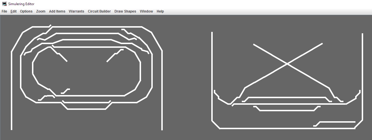
I have been considering how to handle the crossing in JMRI. I have made a little experiment in Panel Editor, where I simply has been drawing the crossing as two track pieces representing the same OBlock and drawn as a cross:The signal is controlled by Signal Mast logic. And in my experiment I have set the rules so that the “approach-block” must be occupied and the two crossing blocks must be free in order to get green light. It works – at least in the simulator:The mast shall of course not be both source and destination. But it was only a quick experiment.

The crossing actually consists of two pieces of track without electrical connection to each other. I have thought of using that fact to have a sensor for each direction and then add some logix in JMRI to implement an emergency stop if both tracks are becoming occupied. I hope that could prohibit train crashes.

It does not seem that one can turn the layout off from Logix. But it is possible to execute a Jython script. And it is possible to switch all track power off  from Jython. See https://github.com/JMRI/JMRI/blob/master/jython/AutoLayoutPowerOff.py

The entire crossing need to be one block, though. Otherwise, two warrants could allocate the crossing at the same time and trains would potentially collide.

3etager_fase1_170201

The split into blocks is as a whole being considered, so that I can begin laying tracks:The signals on the drawing are the logical or virtual signals – those to be used by JMRI to make Warrants work. The relatively few physical signals to be placed on the real layout will only be on the visible part of the layout and not all the virtual signals will be represented by physical ones. Some physical signals may even not correspond to a virtual signal. For example there shall be only one entry signal to Skive H from left to right even though there are two logical signals – one for each track.

January 29

IMG_0155
image
image

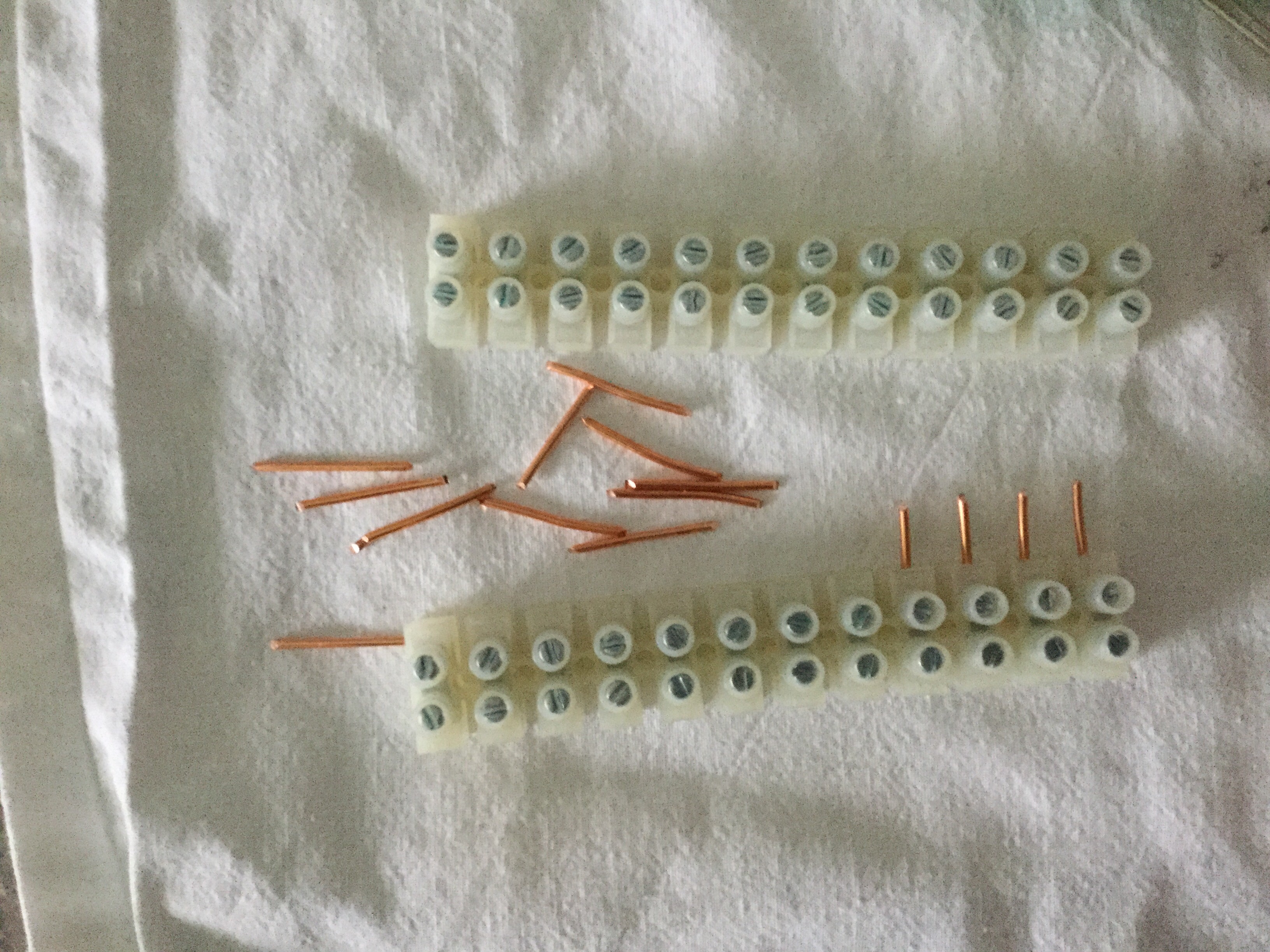
I have started all sorts of small tasks. Right now I am preparing to mount the wiring. I wish I had bought connector strips like these for my current sensors:They would make it much easier to disassemble and reassemble if a module has to be taken out for repair. But no need for wining. I will just make some myself by cutting copper wire from installation cable into tiny pieces:And then I have begun the noise dampening.I am almost done with the lower level. Only the front corners and the flex track are still missing:I am gluing the green stuff with wood glue. I have bought a liter. I am trying to use only a very thin layer, but I am still using quite a bit of glue.

January 30

I have started to define the layout in JMRI. I have chosen to use LocoNet Simulator instead of ECOS. That way I can define the entire layout and test signalling without even connecting to the ECOS. It is true that I then have to do “global-search-and-replace” on all sensors when I will start using JMRI with my physical layout. But I have tried that operation before when I replaced IB-COM with ECOS.

PanelEditor

Until further, I have defined all Sensors, Turnouts, OBlocks, Portals and Paths. I have done so directly in the tables in JMRI. That is easy. Easier than doing it through tiny dialog boxes in Panel Editor But now comes the hard part, i.e drawing the layout in Panel Editor. I will not – at least initially – draw the layout in Layout Editor too:The tricky part is that there are several icon sets to choose from and not least that Panel Editor is not absolutely flawless. Special attention has to be given to the fact that even though one chooses a turnout and a set of paths in the “insert” dialog, one shall not count on getting what one asks for. One has to right-click several times on each icon and choose “edit” to make the icon represent what it is supposed to. Of course that is an error in Panel Editor. And of course the error can be corrected. But somebody else need to do that.

February 4

Now that the Saturday cleaning is over and done with, it is the time to build servos into the turnouts. I will only make the turnouts that I need right now.

For the purpose, I have sawed tiny pieces of 4 mm acrylic / plexiglass. Two pieces per servo – one 25×28 mm to mount the servo and one 28×10 mm to hold the piano wire into place.

Once more, I have tried using a jigsaw to cut the plexiglass. It doesn’t work. The blade becomes so hot that it melts the plexiglass. And thereby the plexiglass glues itself together again right behind the saw blade. So I am using a manual saw instead. It is not getting pretty. But that doesn’t matter. Everything is hidden underneath the turnouts.

image
image

In addition, I have been cutting the servo horns to length, so that there is room for them inside the turnouts. In addition, I have lined up double adhesive tape etc.:Ét voila:I have finalized the noise dampening on the lower level. Tomorrow, I will be laying the track including sawing holes in the plywood underneath the turnouts to make room for servos.

Then plywood for Skive H need to be sawed and mounted using threaded rods. And then comes wiring and electronics.

February 5

I have spent most of the day sawing holes for servos and finding the right track pieces so that isolation between blocks is according to plan. In addition, one of the old turnouts had to have it’s 1 mm piano wire exchanged with 0,6 mm.

image

But now the first oval is in place:I have spent the last hour of the day soldering the final 6 current sensors for S88-N module #2, which until now onla had 10 current sensors.

February 6

Wiring for the 6 new current sensors is done. Now I only need to test the entire module. But that will have to wait a little.

February 7

I have added blocks 27 and 28 to JMRI according to the track plan above (January 27). It was not easy. There seems to be an error in JMRI Panel Editor so that one cannot create an OBlock without ensuring that the entire layout is interlinked with Portals and Paths.

Or rather: The problem is the exact opposite. One is allowed to save a layout without this coherency. But when the file is loaded during JMRI startup one gets a very long and cryptic error message and no part of the file can be read. I.e. the entire layout is lost.

Luckily JMRI stores a series of backups of the layout file. So I could copy one of these backups and then try again. I managed to get through in the third attempt.

image

Apart from that, I have started a small series production of 4-servo / turnout decoders:

February 8

I have defined all signal masts as virtual in JMRI. And I have placed the first few in the panel and defined signal mast logic for those.

I will not be coming to the physical signals until a later stage.Right now the only purpose with signals is that SCWarrants need to have signals to run trains.

Work on the servo decoders is progressing.

February 9

All signals are placed on the layout in JMRI. In addition I have been adding block numbers and turnout numbers so that they are visible. Only a small portion of the signal logic is defined.

I have discovered that the guy who originally made Warrants in JMRI has removed my SCWarrants. To say it in the nicest way possible, I am less than satisfied with that. But it looks as if he has been making the original Warrants signal aware, so a test must reveal if I should be happy or mad/sad, i.e. if I have to start over again to make Warrants work on my layout. I have a hunch that at least the functionality with not having to record throttle commands is missing.

image

It is going forward with the servo decoders. I still haven’t mounted any active components or programmed any micro controllers:

February 11

The last few components are now soldered. Only micro controller programming and wiring is left. But that is going to wait until I have added a board for all the electronics.

image

In the meantime I have sawed the plywood for Skive H. I just need to glue and screw the three pieces together:

February 12

I was in Bauhaus to buy a few 3×13 mm screws etc. Thereby I can assemble the plywood for Skive H.

image

Besides, I have at long last added the board for electronics in term of the leftovers of the 9 mm plywood board. I will have to see if it is too thin to screw the electronics into place. But now it is there and I have moved the layout back to the corner where it belongs:In addition, I have been working with a hole saw tomake holes in the baseboard for wiring back and forth between ECOS and the electronics board (or between the front and the back of the layout). And then I have been putting a power rail on the baseboard.

I am considering if I should buy something like this https://www.elvvs.dk/c/ledningskanal-m-slids-3393/ or if I should glue wires to the baseboard, continue with the hooks I used on the prototype or what.

At least, it is not going to be allowed to become a spider web of wires like the prototype.

Late in the evening, I finally found the solution and has now ordered cable binders and a roll of Velcro from AV-CABLES. The plan is to attach all wiring with Velcro. The cable binders is for attaching the electronics thatcannot be screwed. For example the power supply for ECOS.

2017 part 1 – Building New Layout – Plywood for Lower Level

See also the pages about the plans for the new layout:

Layout
Landscape and buildings (including semaphore signal)
Wood work, wiring, extended feedback etc.

January 1

Up early. Out for a walk. New Year Concert and Ski-jumping in the Television.

But I also spent time ordering components for decoders etc. from Reichelt and servos for the new turnouts from NiceLED.

January 3

The goods from Reichelt have arrived already.

January 8

This takes time. I have spent the entire day on very little:

I spent all morning buying and collecting a board of 6 mm plywood. For transportation, I had to borrow a trailer. And while having the trailer available, I used it to get rid of the Christmas tree. And then I had to deliver the trailer back again.

img_0148

I spent the afternoon sawing pieces of plywood for the front shadow station and for the visible track at the front as well as marking the arched pieces for the sides:I am not good at arches. So I have been using my ruler for ever centimeter to draw a dot 4 cm away from the track. But now I am ready for the saw.

January 9

The 4 arched pieces are ready.

NiceLED has still not sent the servos. They are caught in customs after arrival in Denmark.

January 14

image

It is Saturday, which means a couple of hours for model railroading. So I am back to being the carpenter. I have been cutting the visible track piece from the front shadow station. The plan is to make the visible track detachable:The arched pieces that shall connect the rear shadow station with Skive H are temporarily stored in the hallway. Same thing with the visible front track.

image
image
image
image
image

Skive H is supposed to be cut from the piece of plywood that can be seen up against the wall:Now I have come to something where I am unsure how to do it. It is my first time joining two pieces of plywood. I am beginning with the joint between the front shadow station and the arch towards the rear shadow station:I suppose I first have to cut the two pieces so that they exactly fit together:Then join them via a small piece of board on the rear. I am first cutting a piece of board from the old layout and then I drill holes in the plywood for screws:Then i glue and join the pieces using 3,5 x 15 mm screws. The board piece is overlapping the plywood with about 9 cm. It seems fine. I just hope that it is not going to be neither to stiff or to weak. I finished joint looks like this:Next joint is worse. Here, I will join 9 mm plywood to 6 mm plywood, i.e. rear shadow station and the arch to wards Skive H.

I don’t know if I should simply do as with the first joint and then align the difference in thickness by adding plaster or whatever on top of the 6 mm plywood. Or should I put something with a thickness of 3 mm underneath the 6 mm plywood and will that become strong enough?

image

Again I start by cutting the two pieces to make a perfect fit (except for the difference in thickness:Note that the rear track shall go down towards the front shadow station while the other 4 are going up towards Skive H.

January 15

Continuing the carpentry.

I have assembled the entire lower oval now. It took a lot of time to adjust the arches so there is room for both the upwards and the downward arches at the ends of the rear shadow station.

I ended up joining the 9 and the 6 mm plywood exactly as the other joints. I then have to adapt the thicknesses by adding something on top of the 6 mm plywood later on.

image
image

Next project is the crossing between the two shadow stations. Here I want to try out the Piko flex track. I have been cutting the ends of two pieces of Märklin track and putting Piko joints on them to join the Piko track with Märklin track. Here is the result:Besides, I have made 4 strips of MDF, 7 cm wide. They are going to be the foundation of the crossing. The 4 strips are going to be joined in the center:The height of Märklin track is 10,6 mm and the height of Piko track is 4,6 mm. I.e. the height will be exactly the same if I add another layer of MDF underneath the Piko track.

January 16

image
image
image

Even though it is Monday, I managed to get home early enoughto get on with the crossing. I have gotten it all to fit together and I have glued and screwed small pieces of plywood underneath the 4 “corners” where the crossing shall join the rest of the layout:The center is cut to fit and a piece of board has been prepared for the assembling:And the “corners” er as mentioned even more ready:But now it is time for watching TV. It is a hobby and there has to be time for other activities as well.

Last message from NiceLED is that he has been clever enough to ask the customs which documents they need. So now there is hope to see the servos within a week or so.

Next time, I suppose I will order in a shop that has the servos in stock inside the EU. For example Hobbyking. It doesn’t mean that I would advice against NiceLED. On the contrary. He made it very clear on his homepage that the servos were not in stock and therefor the delivery time was unknown. So I could just have ordered elsewhere.

January 17

image

The MDF for the crossing is done. Only problem is that the MDF is so hard that screws do not go into it, but keep having their heads above the surface. We will see if it becomes a problem once I lay the track:The glue will get time to harden until tomorrow. And then I am ready to rise the rear shadow station to elevation 5 cm. Or rather, I will have to find pieces of wood or similar that provide the right elevation. The final fastening will have to wait until I have been able to do test driving.

January 21

NiceLED has finally received the servos and has already sent them to me.

image

To do some initial test driving with something similar to the correct slopes, I have put a lath underneath the rear shadow station. It is thereby elevated 1 cm to much, but I will try something out anyway. Good old Märklin 3060 Santa Fe first:As expected, it can do anything. But what happens if I attach 4 wagons to it? And what about the Heljan IC3 train? I also have a locomotive with low hanging snow plows that shall be tested with and without wagons.

image
image

Next test: 7 Lima B wagons after the Santa Fe locomotive. No problem. Both pulling and pushing the wagons:The IC3 train seems able to “climb the mountain”. When it can do it, anything can:The IC3 train has not become any more stable than last time I wrote about it. After a few successful rounds back and forth I found courage and increased speed. That made both drive shafts loosen themselves from the boogies. I may be possible to fix with Superglue. But it is not good enough, Heljan.

On the other hand, I don’t think it has anything to do with the layout, so I have just put the IC3 train back into it’s box. After having put the driveshafts back into place, of course. Then we will have to see about the future of the IC3 train. Maybe I will sell it. It is nice and new. And it will probably run fine on a bigger layout without R1 curves.

As mentioned, I have an other locomotive with low hanging snow plows. It runs fine both back and forth. Also with the single compatible wagon I own.

But it cannot pull more than this single wagon. It doesn’t have rubber tires and it only pulls on two axles on one boogie. I have two axles with rubber tires for the locomotive. And then everything is going to be fine, I am sure. There is not room for more than 3 wagons on my layout anyway.

image

All in all, I will conclude that 5-6 cm elevation is OK and I will attach the rear shadow station using pieces of the lath and a bunch of screws:And the train still runs.

During the evening, I corrected a small problem in JMRI: An other JMRI+ECOS user wondered why he could not transfer locomotive definitions, that he once had uploaded from ECOS to JMRI, back to the ECOS, where he had now by mistake deleted them. And that is of course a point. So now I have changed it so that a locomotive definition can be put back into ECOS provided that the DCC address is not already in use in ECOS.

January 22

I had to test the slopes again. And all of a sudden, the good old locomotive can no longer push 7 wagons. Not even 5. The derail. In return, I got verified that a Lima B wagon is durable enough to fall a meter down onto the floor without any damages.

It turned out that by switching two wagons, I managed to once again push 7 wagons uphill.

image

And still – with my layout, 7 wagons is without interest. 3 is maximum:I am in full progress to ensure the right elevation all the way round. I am not doing it as thorough as described on stahlbahn.de. So my layout is not going to be easily adjustable in elevation.

image

Instead, I have calculated where it fits with 1×15 mm, 2×15 mm and 3×15 mm round the arches:
It fits with a57x388 mm lath at the high edge under the rear shadow station, where it is only the 9 mm plywood.

image
image

The same lath but on the low edge and supplemented by a piece of 6 mm plywood fits underneath the joints in the end of the shadow station:And the crossing has been raised a bit too:So far, I have only screwed the wooden blocks to the base board but not the plywood to the wooden blocks. I have thought of only attaching the plywood very few places.

That way, it is easy to take everything apart again. And besides, to many screws may serve to transfer noise.

POSTSCRIPT (OCTOBER 2017): IT WOULD PROVE THAT THIS WAS CUTTING CORNERS. FOLLOW DESIGN RULES, AS FOR EXAMPLE MAX. SLOPES OF 4%. MAYBE IT WOULD WORK WITH 5-6%, WHICH CORRESPONDS TO THE 5-6 CM MENTIONED ABOVE. BUT THAT WOULD REQUIRE AN EVEN DISTRIBUTION. AND EVERYTHING NEED TO BE ATTACHED FIRMLY SO THAT NOTHING IS LOOSE, SHAKY AND ASKEW.

2016 part 4 – Building New Layout – The Base Board

See also the pages about the plans for the new layout:

Layout
Landscape and buildings (including semaphore signal)
Wood work, wiring, extended feedback etc.

November 25

I have printed phase 1 – i.e. the lower 1½ level in 1:1 using SCARM. That gives a bit of impression regarding how difficult or easy it is going to be to reach the lower level track from beneath. And soon I will use the printout as template when I cut plywood for the track.

In addition, I have been to Silvan to buy a bit of wood and some threaded rod (M4).

img_0128

I bought a tiny piece of MDF instead of plywood. They also had a similar small piece of plywood, but it was skew. In addition the MDF actually feels sturdier and stronger that plywood.

It has to be tested first. Maybe MDF is too stiff and hard? Or maybe there are other problems? That is why I have only bought small samples of the material to be used.

December 2

I have now bought enough wood for the base frame. Silvan had a big pile and I bought all those that I deemed of good enough quality. And that is just enough for my design:

image

The strange spot where three boards meet is an enforcement that serves two purposes: It shall make the entire construction sturdy and it is where the legs are to be attached. Even though there is only one such indication on the drawing, there shall of course be 4 legs on the layout. These are by the way re-use from the prototype layout. They are height-adjustable round steel legs from IKEA.

Besides, I have bought some fittings. Among them some meant for making a drawer for a keyboard. They are now meant for the ECOS.

As anybody can see, all this is so far only in planning mode. Nothing real is happening. I am to busy with work and much else.

December 18

Finally a day with a bit of railroading time.I have cleaned up on the prototype layout and made a film where the trains are running purely computer controlled, i.e. JMRI / Warrants combined with a simple Jython script.

image

Besides, I have been using the cross-cut saw to cut the boards into length. Now I just need to put some screws in and my work with the new layout is ongoing:Here the boards are shown on the high edge approximately as the finished base frame will look like:

image
image
image

To screw it all together, I have been measuring, then drilled 2 holes of 3 mm in the longer boards for each joint. Then I put the joint together using clamps:After which I drill as far as possible into the end of the short board with a 2 mm drill and attach with 4×50 mm screws:I found that it is best to start in the middle and work my way out toward the sides and finish with the ends of the base frame.

Today I didn’t manage to put the last 4 of the shortest pieces on, and thereby not the ends either. Hopefully, I will get time for this during Christmas.

December 28

image
image

I managed to finalize the frame today. Now it only need legs, before I can get on with building the new layout. For that I need to break down the old layout so that I can re-use the legs, the track, the electronics and not least the space.One last view of the prototype layout before it is broken down:Besides, I have been at Lokdoc in Brøndby to buy the additional track needed for phase 1.

December 29

image

All electronics and all track is uninstalled:Now I need to put in all in boxes so that I can remove the old baseboard and install the new base frame.

image
image

Ready for carrying out:And install. The legs have been transferred to the new base frame using small pieces of the old base board:Now I only lack……. everything. I need to make a board for the electronics. The board must be attached to the wall behind the layout. Or maybe at the back of the frame? And it must be designed so that electronics and wiring becomes manageable. I have to build more decoders and S88 modules. Wiring must be done. Plywood for the track. Servos must be built into new turnouts. Track must be laid. The new layout must be defined in JMRI. Etc. etc. But now the process is ongoing.

I need to build the following electronics:

  • 3 decoders for turnouts
  • A distribution frame so that I can connect each individual decoder or the programming track to the programming output on ECOS. My idea is to use these RCA sockets and corresponding plugs.
  • The rest of the current sensors that can be accommodated on the board that I already have.
  • Maybe another S88 module including current sensors. My first division into blocks tells me that it is not necessary for phase 1. But I am going to need it for phase 2.
  • Servos in 12 new turnouts out of which one is a 3-way turnout needing 2 servos.
  • I need to find some kind of connectors for detachable modules.

December 30 and 31

I found a small piece of plywood in Silvan. I thought it was 6,5 mm, but it turned out to be 9 mm. I have cut a 22 cm strip to be used for the rear shadow station. It is somewhat stiff, so I will use 6 mm for the rest of the layout.

First Real Layout 2 – Landscape and Buildings

In the following I will describe the elements that I am considering at the moment for my layout. I imagine they could be placed approximately like this:

3etager_161102-huse-m-v

The pictures on this page are from various sources, among them Tage Falkenberg, Erik Trudsø and EVP.

Spøttrup Station

The history goes something like this: We are in 1990 and have just realized that SVJ (Skive Vestsalling Jernbane) still exists even though in real life, it disappeared in 1966, when I was 2 1/2 years old. However Spøttrup station (that use to have a rather large depot building, shown on the following pictures) has been reduced to only 2 tracks and only a fraction of the depot building.

remisen

I am considering only to build the part behind the port to the far left on the picture above. There is a better view of that part (seen from behind the building) here:

remisen-3

To fit the station reasonably correct I will add a small siding pointing back towards Skive, but only going into the depot building. I have no intention of building the turntable or the other tracks. It would take up to much space. See this track plan of the real Spøttrup Station:

img_0103

I am not sure if I am going to build the station building itself. The real building looked (and looks) like this:

img_0104

Heljan’s model of Videbæk station does of course nok look especially much like Spøttrup station. And it is (as I guess is true for all buildings from Heljan) to small. Anyway, it might as a starting point become the station building on my layout:

img_0105

Since Spøttrup station is becoming a time warp, it also gives me an opportunity to have a semaphore signal. Such a signal had it’s place at Spøttrup station:

img_0106

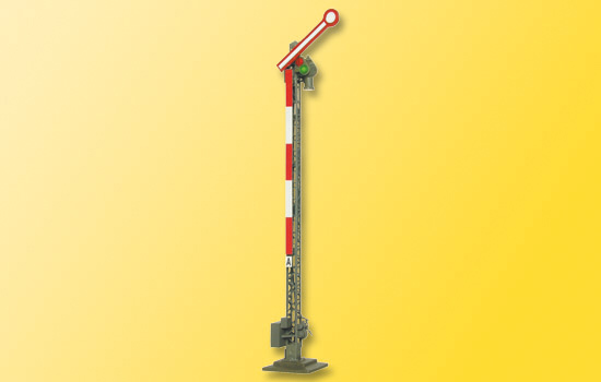
The signal had only one arm. What might look like the second arm is really a luminaire. As far as I know, one cannot buy such a Danish signal. There has over time however been people producing the arm, so that one could place that on a signal that has been produced as a German signal. My idea is to settle with a Viesmann 4500 (250 kr), which for example can be bought at Lokdoc.

The signal requires a decoder for magnetic articles. And even though I can build one myself, this might one place where I buy an ESU SwitchPilot (260 kr).

Besides, the manual states that a transformer with 14-16V 0,7A is needed. But I don’t need that. All my signals are to be controlled by the IB-COM. And that has a more than adequate power supply.

Märklin 70392 could be an alternative. But it is as expensive as both Viessmann 4500 and ESU SwitchPilot.

I could also equip one of my Paco decoders with a darlington array as a driver and different software. The darlington array is 3 kroner, and I have it already. See the diagram here, even though I would modify it to not have a separate power supply, but drive the signal directly from DCC power.

The signal should be painted so that the mast is grey and the arm red as it should be for a Danish signal. I think that would be good enough for me. The signal looks as this:

img_0109

Whereas a correct Danish signal would look like this:

img_0108

I do see that there should be holes in the arm, but a solid red arm is good enough for me. The German read and white piece on the mast must be cut off. And the same thing with the object near the ground which is supposed to look like an electric motor.

See this instruction from Freja.

Besides there were no red and green lanterns on the signal in Spøttrup. But there seem to have been on other Danish signals. So either I have to add to the story that at some point in time, these lanterns were added to the signal, or I shall manage to cut them off without destroying the rest of the signal.

The real signal at Spøttrup looked like this:

img_0110

Skive Station

The real Skive station looked like this on the tracks used by SVJ:

img_0111

Note the signals. I intend to only implement a single PU signal at the edge of the platform towards Spøttrup.

The signals on the main tracks will be similar to those still on the same track today: I-signals with 4 lanterns and U-signals with 2. There still seems to be a PU signal with 6 lanterns towards Struer. But I think I will forget about that.

The station building looks like this:

img_0112
img_0113

As it can be seen, the station is built into a slope or a hillside, so that it is 4 storeys high towards the platforms and only 2 towards the parking lot.

I have bought Heljan’s version of “a modern station”, that is not in production anymore, but still available from Togdillen. It is 2 storeys both sides, but seems to be inspired by Skive station. The model is 48 cm long, which probably is not enough to be 1:87, but more than enough for my small layout. The model looks as this:

img_0115
img_0114

The facade towards the parking lot can be made a bit closer to reality if the DSB wings are put above the entrance instead of on the gable, which by the way shall be “clean” as in the real world.

The facade against the platforms can also be less wrong by avoiding the canopy. But the real station is 4 storeys, which the model is never going to be.

I have thought of placing the building at high enough elevation that the track to the far left towards the rear shadow station “disappears” under the station building. I don’t want to make mountains for that trick in a flat country as Denmark. And at the same time, Skive Station will reside way above the track as in real life.

I still don’t know what to do with the doors on the model in the platform side. Maybe I will paint them so they look like windows. Maybe I will make them into Venetian balconies with bars in front of them.

Likewise, I am not sure about the covered stairways down to the platforms. I may be doing something entirely different than the real world. We will see.

Other Elements

I am living in Taastrup in a house from 1997. So it has obviously no place in a landscape near Skive anno 1987 / 1962.

But I would like to challenge myself by building my own house, so I will find a place for it. Maybe in Rødding, which is the village where Spøttrup station is.

Besides, there need to be a road for my single Faller car. Maybe a circle from Skive station out through the city, crossing the rails at the end of Spøttrup station, continuing behind the railway and through Rødding, under the rails, which must then be on a bridge and back to Skive. For a bit of added fun, I could add a “turnout” in Skive leading to a parking place, where I can start and stop the car using an electro-magnet.

I would also like a lake, where I can try to make water. And then somebody can be fishing and somebody can be bathing. It will bring life to the layout.

Maybe a camping site by the lake?

It seems very modern to make a tivoli. But I don’t think I want to use space on that.

Skive Town

I am considering to build the post office as well as the square next to it. At the square there is an ice skating rink in the wintertime.And it could be fun to make ice skaters that actually move. It might be that the rest of the layout is summer while this one element is winter. But so be it.

The square could also give room for a “pølsevogn” (particular Danish kind of hotdog stand) – even though I have no recollection of such a thing from Skive at those days.

To make a complete town, there need to be more houses in Skive. But some kits from e.g. Faller would be sufficient. Even though they are German houses, some of them are somewhat similar to Danish buildings from around 1900.

Elevation

As already described, Skive station resides high above the front tracks. From there the terrain raises even higher both moving to the right and to the rear of the layout. The town of Skive is situated on this slope.

Rødding might be placed high enough to make it possible to make a road bridge across the track?

Rødding Village

Rødding consists of the station building and a few houses more.One of those house could be the one where I was born in 1963. The house is similar to house number 2 from the left on the picture below:

img_0119

The was hoever only a single window in one of the gables (at the top floor).The dormer window (which is still there) is a bit wider and consists of 7 single pane windows. The windows in the facade had 6 panes like this one. There was however an arch at the top as far as I remember:

img_0118

Rødding also had an ice cream parlor selling Grotte ice cream. It was not this one, but it probably looked similar:

img_0120

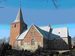
The church is almost next to the station – opposite the village. I will not build the church right away, but it can become a fun challenge at a later stage with it’s varying building materials from different ages and with the pointed roof on the tower:

img_0121
img_0123
img_0124

Along the road between Skive and Rødding there are fields and a couple of houses. One of them could be the Faller house I have ordered just to start with something.

In addition, I can make a stopping place for the train. There were a handful of those in addition to real stations between Skive and Rødding stations.

I am not sure if there will be room for Spøttrup castle. But it could be fun:
img_0126

The brickworks at Nymølle is also among my very early childhood memories. It disappeared in the late sixties. Today, only the chimney is left:

img_0125

Maybe I could make room for the ring furnace some time way out in the future?

2016 part 3 – Thoughts About Model-houses and Model-cars

October 17

Tonight I am just reading a bit on the Internet. Not really doing anything. But check out this Swedish homepage: http://jorgenedgar.se/kurser/x10/start.html. He makes locomotives etc. by order. And he has made a lot for himself. Among it pretty much any Danish diesel locomotive in scale N. And he makes them out of plastic and cardboard. I guess he spends a lot of time on each locomotive…

October 22

There is not going to be much model train this weekend. The goods I have ordered from NiceLED for mounting interior light in the Lima B wagons have not arrived. I suppose they are on vacation.

But I am reading (and writing) a bit on the Internet. Right now, I am reading niels-modeltog.dk and how he has built Svenstrup Station out of Heljan brick wall and roof plastic card and Auhagen details. I suppose the result is nicer than it will be, of one builds out of cardboard, where the contours in walls and roof are non-existent or wrong.

The plastic card can be ordered from Heljans homepage (delivery 85 kroner). Windows are another problem. I wonder if one should still make them out of cardboard? Or can I find some made from plastic? Locdok seem to have a good selection of windows, gutters etc. from Auhagen. But naturally that is German, which is a different style than Danish.

I am not sure how he manages to make corners, window openings as nice looking as is the case.

See also Sydvestjysk modelbaneklub from Ølgod. They have made their own cardboard houses. They have made some out of kits from Epokemodeller and they have been modifying and building Faller plastic kits.
Some day, I want to build houses from Spøttrup – the station (see this film from Spøttrup lokalhistorisk arkiv), Nymølle Teglværk (Sydvestjysk Modelbaneklub have been building something similar, a chimney is available from Faller), maybe Spøttrup Borg?

October 23

From time to time, I can act fast. So now I have ordered Faller 130507, which is a plastic kit for 2 German houses, which have to be painted to look Danish.

And the plan is to buy a bit of Heljan brick plastic card at Hobbymessen in Rødovre in two weeks. It seems a bit stupid to pay 85 kroner for delivery of a couple of cards priced at 75 kroner. Maybe I could get my local model train dealer to obtain them. But right now, it does not seem that anybody nearby keep them in stock

I.e. I will stick to my plan of building out of cardboard for concrete buildings, but brick buildings will be made out of plastic. Maybe I will do everything in plastic when it comes to it.

October 24

I was at Togdillen in Vanløse after work to buy a couple of pølsevogne (a very Danish thing) and a bit more. They have a lot of stuff that cannot be found in their web shop. For example a small selection of wood strips, brass pipes etc. And a larger selection of (very thin – 0,5 mm) profile plastic sheets, for pavement, steel roof etc.

They did not have any Heljan brick wall sheets. And I couldn’t immediately find any standard plastic sheets either. But they probably have them anyway, for I saw an Evergreen display like the one below. And I have read here, that Evergreen is the best there is:

evergreen-plasticard

Evergreen sheets and profiles can also be bought in the Internet in Denmark at På Sporet. However, they charge 100 kroner for delivery.

Togdillen has a lot of stuff that is no longer being produced – such as the “pølsevogne”. And they also produce some nice things themselves. For example a lot of houses from Korsbæk / Matador (a very popular TV show from the 80’ies). And they still have a few IC3 trains, that they have produced out of Heljan parts.

November 5 – Hobbymesse etc.

I was at Hobbymesse in Rødovrehallen today. It was mostly a shopping trip, where I bought the above mentioned kit from Faller with 2 houses.

Besides, I bought some plastic sheets, that are not Evergreen, but something cheaper from Witzel Hobby. We will have to see if they are any good. Otherwise I found out that Kystbanen in Charlottenlund is having he entire selection from Evergreen.

I bought the Heljan brick wall at RC Kongen, who shares address with Heljan, but is selling the products cheaper and with cheaper delivery.

I succeeded in talking with somebody from Risløv Hobby about airbrush. It is not to be used indoor, unless one has an effective suction system / painting cabin, since a fine fog of paint is spread several meters away.

In the afternoon, I was at a postage stamp exhibition in Birkerød. There I saw the 3modul.dk club with a big model train layout. I had a good chat with one of the members, which made me consider joining the club (100 kroner per year).

But more importantly, he teached me how to mount 4 LEDs in a car: Connect all 4 in series and connect them directly to a 5V power supply, such as a USB charger.

And there are two possibilities:

Either the car is equipped with head and tail lamps with “real glass”, where the LEDs can be placed behind the glass.

Or (and that is almost simpler) drill a 1 mm hole and use one of the very tiny LEDs that are bought with copper wires already attached (they are smaller than the 1 mm hole). The LED is simply put into the hole (from the inside) and attached with a drop of transparent glue that covers both the LED and the hole. The glue he uses is Micro Kristal Clear, which can be obtained from (among others) Togdillen.

He also thought that the cheapest place to buy the LEDs is at ledbaron.de. Web shop: http://stores.ebay.de/ledbaron I can see that they also has the very thin wire as well as tiny connectors. Or one can search for “LED 0402” at mouser.com.

November 17

I have just seen a strip cutter from Faller, model 907004, for not a whole lot of money here.

Beside that absolutely nothing is going on from my side. I am way to busy at work etc.

November 24

I have sold my MR tog, even though it had become quite nice and well-working with thin wires to connect the two wagons. I cleaned the wheels, lubricated the train using fat from Trix and attached new rubber “tires”. But of course, it is still a Lima train made 100% out of plastic, so I did not get that much money from it.

I hope the new owner will be happy for the train. And then I might buy a new MR/MRD train when Mck starts producing them as promised.

Besides I am “looking at” wood for my new baseframe. And I have been printing the layout in 1:1 so that I can start the build. I have not yet ordered track etc. But I plan to have the wood available so that I can start building during Christmas.

2016 Part 2 – Model Building Plans & Lima MR Conversion

End of September 2016:

It’s good to make plans. And I have plans both in the long run and for the season that will start soon.

Long Run – Layout

For the long run, plans for a larger layout are in progress. Jørnebanen is still the great inspiration. I haven’t got room for his new layout, jornebanen.dk. But the old kamstrupvej.dk might be pushed in. However, I would like a road to my Faller car, and my houses must be in a completely different style. And I wonder if I am able to divide the layout into for example four detachable parts, so I will be able to build details and make various repairs in smaller pieces?

Besides the inspiration from Jørnebanen, I also wonder if I have to let the layout consist of Aarhus H at the crossroads of the visible part of the track and let a reversal stretch over a shelf along the wall and around a corner and down under a desk and let the other end of the railway station disappear below to a shadow yard? A shadow yard is perhaps very good, but doesn’t it become a little tame with just a big railway station as the center piece?

Short Run – Layout

But a new layout will not be in the coming season. I’m not done making prototypes. However, it may be that I extend my prototype with an upper floor, and also do some prototyping regarding modularization. It’s something with 25 pole connectors, cutting rails and something that is accurate enough for the trains to cross the borderline between modules.

When building several floors, I have to figure out how much slope I dare to make on the rails. For example, if I will have a maximum of 2% slope and there must be a 10 cm level difference (trains and rails are about 6 cm, and there must also be room for little plywood and a servo or a wire that sticks beneath the upper floors) 10 cm * 100/2 = 5 meter rail.

A half circle with R1 curved rails is only pi times 360 mm or approx. 1.13 meters. In reality, slopes above 1.8% are only for mountain railroads. But model trains has so far I can read no problems with 2%. You can also go up higher – especially on a straight line, where you could go up to 5%.

New calculation: Let’s use 9 mm plywood and thereby get down to 8 cm level difference. At 3% there is a need for 2.7 meters. At 4% 2 meters. But it is still very much for a small layout. It takes a lot of trial and error and it certainly also requires that where two levels are to cross each other, one level must be “on the way down” and the other “on the way up”.

It is probably not entirely coincidental that kamstrupvej.dk operates with both basement, ground level and first floor. It’s actually half floors, that is, for example 4 or 5 cm level difference. And as far as I can see, he uses almost 3/4 circle to come up or down, i.e. about 1.6 meter rail. At 4 cm level difference, it gives 2.5%. At 5 cm it is just over 3%.

But now I am again thinking long run. I’d better stick to making a single stretch with adjustable slope – both a straight and an arc. Maybe just let a siding have the slope? It must be easily possible using Woodland Scenic stuff: http://lokdoc.dk/risers-420

Time and Place

I have determined that the time is 1987 +/- 5 years, though with a single steam-driven museum train.

The place is Denmark, however, with the visit of another museum item, my old American Santa Fe train.

And of course, there is also the Skive Vestsalling Railway, for which I have a tiny train (“rail bus”) and where I both intend to build Spøttrup castle and Spøttrup station. It was shut demolished in 1966, but has to be brought to life again on my layout.

Desirable Rolling Stock

As mentioned, my layout is Danish, anno approx. 1987. That is, I can use the following rolling stock:

  • Green and/or red/black MH/MT for switching and freight trains.
  • Red/black ME/MY/MX/MZ for especially intercity trains, but they can also be used in other passenger trains as well as freight trains.
  • Red MR/MRD. The MR train was not painted white until 1995 or later. And the blue/grey IC3 and MR tog was in the mid 0-es.
  • Red MA (without wings on the front, but with white DSB logo – was painted silver in 1984. But he red one looks better)
  • A and B wagons as well as a single Ag, which were in use in intercity trains way up into the 1990-ies
  • The white IC3 train, which was delivered in 1989/1990

Freight trains is not my big thing. But I suppose I will need a freight train anno 1987 at some point in time.

And maybe some older wagons -preferably passenger wagons, so that my litra N steam locomotive can get something to haul. It was a freight locomotive while it was in use. But if there had been preserved one of them, it would probably be used for passenger trains as well.

Short Run – Software

In the short term, I will declare my Signal Controlled Warrants, which I implemented in JMRI in the 15/16 season, a success, and therefore not make more control software.

On the other hand, I need to do something about the locomotive sounds, which in a sense are also part of JMRI. In addition to writing some documentation for the file format with the sounds for virtual sound decoder, I’m going to add sounds for my MH locomotive and maybe also to the MR train. Santa Fe and BR216 can do with the existing JMRI sounds so far.

The problem is to obtain sounds without violating anyone’s rights. It has to be worked on. The sounds should consist of engine noise at different speeds and the transitions both during positive and negative acceleration. And in addition, for example screeching brakes, door noise, station messages, etc. Motor noise is the biggest problem. The other sounds are available online in editions that anyone can freely use.

Short Run – Model Building

And then there are my signals, where I’m not completely satisfied with the prototype I made in 15/16. I’m going to try again with a more realistic mast, thin copper wire down the mast and the ugly resistors away from the back of the signal head.

If I get my Faller car to run? Time will tell. It depends if I come so far that I get a road built.

First and foremost, the season is about model building. I want to build houses of paper. First, any of the houses that can be downloaded at http://www.solvangprivatbane.dk/ and then a house of my own design.

The procedure can be read on modelbane-piger.dk, from which I also bought a CD-ROM with a little more than that on their website. I need some materials:
– Cardboard / cardboard of 1.5 mm. Already purchased in Bog & Ide.
– Some glue to glue printed facades, etc. on the cardboard. First try done with a UHU Photo Stick (an acid-free adhesive stick) purchased from Bog & Ide.
– Plain white glue to glue the different parts of the house together. However, Witzel’s hobby suggests something different in their construction manuals.
– A scalpel and a cutting pad. The wife claims that we have that already. Modelbane-piger suggest a hobby knife.
– Steel ruler to guide the knofe while cutting.
– Corrugated cardboard with 2 mm waves. I will look at Panduro Hobby.
– Some watercolor paint (tempera blocks) to paint roof. The lady claims we have it. Otherwise, it will be Panduro.
– Matt spray lacquer to make printouts or watercolor paint more stable.
– Color samples on ordinary wall paint if something is to be totally smeared into paint.
– Clear plastic or PVC sheet 0.2 – 0.3 mm for window glass. It can be purchased at modelskibet.dk.
– Wood or plastic strips of 1 x 1 mm corresponding to 10 x 10 cm (exactly 8.7 cm) bars in real life. Maybe 1.5 x 1.5 mm, corresponding to 13 x 13 cm in fact. Modelskibet.dk is probably the best bid.
– Water sticks or straws (halved to become gutters). Otherwise, steel profiles can be purchased at modelskibet.dk.
– Pin copper wire (from wire) such as handrails, drain pipes, etc.
– Strange little things.
– Jørnebanen makes a nice sidewalk. For this purpose, plastic card and cobblestone are used, which may also be this one.
– Asphalt should be possible to make out of black sandpaper. But it will probably ruin the Faller cars. A smooth painted surface is probably more to “their liking”.

Perhaps my first self-designed house should be Borgen Trinbrædt. See http://evp.dk/index.php?page=svj—stationer

Next, I want to build the house I live in. And it must be including the garden, the driveway, the greenhouse, the furnishing inside the house, lights, etc. etc. The model train will not be able to drive, but there may nevertheless be one around the Christmas tree.

In addition to the houses, a number of different surfaces, such as pavement, gravel, road etc must be made.

And I want both rust and ballast on a small part of my rails. I bought a little bag of ballast, but I am still lacking paint. And I’ll probably also use a Roco track cleaning block http://lokdoc.dk/roco-185/roco-10915-p1675

In addition, there must be grass. I want to convert an electric flie swatter into a Grassmaster and “sow” some Noch grass.

I guess that is plenty of plans for a single season…………

And yet…..

Maybe I should start all over again. Why not make an almost-copy of kamstrupvej.dk. It can almost be in the same space as my prototype layout. It must be built on a frame, but with the top divided into modules like the city and / or the mountain on jornebanen.dk. Perhaps consideration should be given to having another basement level with a further reversal loop or the like. I must be able to reach all non-visible rails from below, so it must be considered very carefully.

I have found this recipe for the frame http://www.fjordens-naturskole.dk/naturskole/Modelbyg/Byg.htm, which I found as a link here: http://my1287.dk/index.php?option=com_content&view=article&id=191&Itemid=127

And I have been designing a bit in SCARM:

layout

If you “flip the drawing out” so it’s not on several floors, you can better see the principle. The orange is the mountain range, i.e. top floor. The white bottom is the “ground plane”, and then you move downwards through the top white and further down to the blue:

layout-princip

Or in 3 dimensions:

layout-3d

The visible part of the layout looks like this (though it may not be completely symmetrical – maybe the rails should disappear into a viaduct or the like on one side?):

layout_synlig

It should accommodate a couple of cities, a country road (to the Faller car) and some fields, lakes, a campground etc. But it is not yet designed.

October 2016:

October 6

I have begun building a house. That is, I have scaled up and printed a guardhouse from solvangprivatbane.dk and cut and glued the walls on the cardboard. And then my efforts are until further halted.

In addition, I have been shopping for the conversion of my Lima MR train: Last year I bought both an ESU LokPilot v.4, fine LEDs from NiceLED.dk (for front and rear lights), LED strips for ceiling lights in Jem & Fix etc.. I also have lacquered copper wire, relatively thin wire and more. And now I have also bought a NEM652 plug with a wire harnish, so everything should be ready. Hopefully there will be time in the coming weekend.

img_0097

October 9

The Lima MR conversion is on it’s way:

img_2245

I need to get the glue dry in the locomotive so I can get it screwed together.

The other wagon is not yet disassembled. But the LEDs to go into the wagon are almost ready. Only a few wires need to be soldered. And then the diodes must be glued and the wagon will be reassembled.

October 11

MR (locomotive part) conversion done:

Processed with Snapseed.
MR train with ESU decoder, red/white light and indoor light as well.

Now I only need to finish the light in MRD (the other part of the train).

October 14

The MRD is done except for the two lower LEDs, which are not yet glued. Tomorrow it is Saturday and the greenhouse must be emptied for tomato plants. So there will not be a lot of time for model trains. But I guess I might be able to do the last bits on the MRD Sunday.

img_0095

It’s not progressing very well, because I have to steal 1/2 hour here and there. There is much else to do with work, greenhouses, etc.

But now I’m building train rather than electronics. Soon it will be houses and countryside. It will be real model building.

I am also having the guard house. It smells even more of “real” model train.

image

October 16

The MR tain is done and another weekend has passed – mostly with greenhouse, cleaning etc.

In addition to the completion of MR, I have also been cutting the first outer wall for the guardhouse. I am in doubt as to whether the solvangprivatbane recipe is correct. I’m somewhat nervous that I end up with some very ugly corners. Modelbane-piger write that the brick paper must go a cardboards width beyond the cardboard so that it covers the corner of the house. It seems correct. But it’s not going to happen the way I’ve started now. However, it’s not too late to change the method, so I think I’m skipping the Modelbane-piger recipe and cutting out the paper pieces first, then lining with paper and then collecting.

October 17

And now back to wagons: I also have some B wagons from Lima that need some light. It is easy enough, according to digitaltog.dk. Or maybe it’s a little over-interpreted. Now I have ordered even thinner (0.04 mm2) wire, smaller plugs and a function decoder from niceled.dk. And in addition, I’ve previously bought a pair of (Märklin) collector shoes and (noname) powerups from lokdok.dk. Then we need to see how it works. If everything is well, the MR train will also get the thinner wires and smaller connectors.

Regarding the B wagons, it is my intent to equip one of them with collector shoe, tail light and interior light. The next wagon will only get the interior light, and I will use a thin wire and tiny connectors to get power from the first wagon to the next.

I use the Lima B wagons because they can be purchased in large amounts for small sums. Not because I will in the long run use them. In contrast to my MR train (which is good and nice, but of course used), my B wagons are better described as well used.

If I later make a similar conversion of wagons with NEM shafts, I would probably consider using power-carrying couplings rather than wires and connectors between the wagon. Eg. Viessmann 4-pole couplings. But I do not sacrifice money on equipping Lima cars with neither NEM shafts nor links.

Translate »